
TCR Twin-Skin Insulated Metal Roof
- Manufacturer
- Total Cladding and Roofing
- Product
- TCR-TSR-001 / Concept 0.1
- Status
- Current
- Market
- United States
- Latest revision
- 0.1
- Latest file date
- September 7, 2026
- Last verified
- September 7, 2026
- Archived files
- 0
Product overview
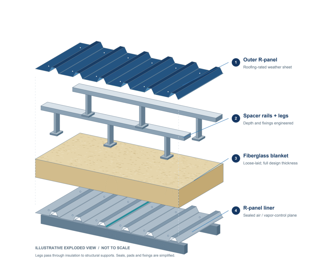
A proposed site-assembled roof with an R-panel liner, variable-depth spacers, loose-laid fiberglass and an outer R-panel weather sheet. Concept revision 0.1 for project discussion; not a tested/listed assembly.
Record scope
This page is the product-level record for TCR Twin-Skin Insulated Metal Roof. It separates this product from similar lines, variants and generations so that specifications and data sheets can be checked against the correct identity.
- Product family: Site-assembled insulated metal roofing
- Recorded applications: Commercial roofs, Warehouses and industrial buildings
- Market: United States
- Manufacturer: Total Cladding and Roofing
Key recorded details
These values summarize reviewed manufacturer information. Use the linked source for tolerances, options, exclusions and complete assembly requirements.
- System status: Design-development concept; not a tested/listed proprietary assembly
- Build-up: R-panel liner; spacer rails/legs; unfaced fiberglass; roofing-rated outer R-panel
- Insulation zone: 5–16 inches illustrated; exact spacer geometry and availability require design
- Thermal basis: Knauf Performance+ cavity insulation; nominal R-16/19/25 at 5/6/8 inches
- Whole-roof U-factor: Not established. Calculate actual spacer, fastener and profile thermal bridges.
- Side-lap liner tape: 50 x 1 mm ≈ 2 in x 40 mil; exact Q131 size subject to supplier confirmation
- End-lap liner seal: 5 x 6 mm ≈ 3/16 x 1/4 in; bead shape and compression require review
- Fire performance: Insulation ASTM E136 data; no TCR roof assembly fire rating assigned
- 5 in insulation / 127.0 mm: Nominal R-16; insulation-only U 0.355 W/m²·K (0.0625 Btu/h·ft²·°F) Insulation only
- 6 in insulation / 152.4 mm: Nominal R-19; insulation-only U 0.299 W/m²·K (0.0526 Btu/h·ft²·°F) Insulation only
- 8 in insulation / 203.2 mm: Nominal R-25; insulation-only U 0.227 W/m²·K (0.04 Btu/h·ft²·°F) Insulation only
- 10 in insulation / 254.0 mm: Nominal R-32; insulation-only U 0.177 W/m²·K (0.0312 Btu/h·ft²·°F) Insulation only
- 12 in insulation / 304.8 mm: Nominal R-38; insulation-only U 0.149 W/m²·K (0.0263 Btu/h·ft²·°F) Insulation only
- 14 in insulation / 355.6 mm: Nominal R-44; insulation-only U 0.129 W/m²·K (0.0227 Btu/h·ft²·°F) Insulation only
- 16 in insulation / 406.4 mm: Nominal R-50; insulation-only U 0.114 W/m²·K (0.02 Btu/h·ft²·°F) Insulation only
Matched current documents
The following current files are connected directly to this product record. Older revisions remain in the archive when moderators retire them.
Design and specification coordination
Use these checks to connect the product record to a complete, project-specific assembly. The manufacturer documents and approved construction documents govern where they provide more specific requirements.
- Confirm panel profile, coverage width, seam or rib geometry, metal type, gauge or thickness and finish.
- Coordinate minimum slope, substrate, underlayment, clip or fastener selection and allowance for thermal movement.
- Verify perimeter, ridge, valley, transition, penetration and closure details with the selected panel configuration.
- Check tested wind-uplift, fire, water and air assemblies against deck type, span and attachment spacing.
- Record manufacturing length limits, field-seaming requirements, finish availability and protection during storage and handling.
Submittal and field verification
A useful product record should allow a reviewer to trace what was specified, approved, delivered and installed. Include the following items when this product is proposed or verified.
- Use the exact product name and manufacturer identifier on the submittal; do not substitute a similar family name.
- Attach the current product data sheet and the applicable installation, safety, approval and warranty documents.
- Record selected options such as size, thickness, profile, color, finish, reinforcement and attachment method.
- Identify the tested or approved assembly and list each adjoining component needed to reproduce it.
- At delivery, compare labels and revision dates with the approved record and archive superseded files instead of overwriting them.
Selection, installation and existing-roof checks
Confirm the exact product name, generation and configuration before using any value on this page. Check the roof substrate, slope, attachment or adhesive, reinforcement, edge and penetration details, accessories, tested assembly and local approval that apply to the project. For an existing roof, compare labels, package records, original submittals and physical dimensions; appearance alone is not enough to identify a product.
Applications and product scope
Recorded applications
- Commercial roofs
- Warehouses and industrial buildings
Record scope
- Product family: Site-assembled insulated metal roofing
- Recorded market: United States
- Product code: TCR-TSR-001 / Concept 0.1
Related services and guidance
Technical information
- System status: Design-development concept; not a tested/listed proprietary assembly (United States / Texas projects; Concept revision 0.1)
- Build-up: R-panel liner; spacer rails/legs; unfaced fiberglass; roofing-rated outer R-panel (United States / Texas projects; Concept revision 0.1)
- Insulation zone: 5–16 inches illustrated; exact spacer geometry and availability require design (United States / Texas projects; Concept revision 0.1)
- Thermal basis: Knauf Performance+ cavity insulation; nominal R-16/19/25 at 5/6/8 inches (United States / Texas projects; Concept revision 0.1)
- Whole-roof U-factor: Not established. Calculate actual spacer, fastener and profile thermal bridges. (United States / Texas projects; Concept revision 0.1)
- Side-lap liner tape: 50 x 1 mm ≈ 2 in x 40 mil; exact Q131 size subject to supplier confirmation (United States / Texas projects; Concept revision 0.1)
- End-lap liner seal: 5 x 6 mm ≈ 3/16 x 1/4 in; bead shape and compression require review (United States / Texas projects; Concept revision 0.1)
- Fire performance: Insulation ASTM E136 data; no TCR roof assembly fire rating assigned (United States / Texas projects; Concept revision 0.1)
- 5 in insulation / 127.0 mm: Nominal R-16; insulation-only U 0.355 W/m²·K (0.0625 Btu/h·ft²·°F) Insulation only (United States; Concept revision 0.1)
- 6 in insulation / 152.4 mm: Nominal R-19; insulation-only U 0.299 W/m²·K (0.0526 Btu/h·ft²·°F) Insulation only (United States; Concept revision 0.1)
- 8 in insulation / 203.2 mm: Nominal R-25; insulation-only U 0.227 W/m²·K (0.04 Btu/h·ft²·°F) Insulation only (United States; Concept revision 0.1)
- 10 in insulation / 254.0 mm: Nominal R-32; insulation-only U 0.177 W/m²·K (0.0312 Btu/h·ft²·°F) Insulation only (United States; Concept revision 0.1)
- 12 in insulation / 304.8 mm: Nominal R-38; insulation-only U 0.149 W/m²·K (0.0263 Btu/h·ft²·°F) Insulation only (United States; Concept revision 0.1)
- 14 in insulation / 355.6 mm: Nominal R-44; insulation-only U 0.129 W/m²·K (0.0227 Btu/h·ft²·°F) Insulation only (United States; Concept revision 0.1)
- 16 in insulation / 406.4 mm: Nominal R-50; insulation-only U 0.114 W/m²·K (0.02 Btu/h·ft²·°F) Insulation only (United States; Concept revision 0.1)
System concept
Four coordinated layers: a sealed R-panel liner, engineered spacer rails and legs, loose-laid unfaced fiberglass blankets and a roofing-rated outer R-panel sheet. Components are selected for each project; the illustration is conceptual and not to scale.
Market: United States · Effective: Concept guide revision 0.1
Verify this information with the manufacturer source
Thermal calculations
The table below uses Knauf published single-layer ratings and calculated multilayer sums. 10/12/14/16-inch options use 5+5 / 6+6 / 6+8 / 8+8-inch layers. RSI = US R / 5.6783; U(SI) = 1/RSI. Surface films, air spaces and thermal bridges are excluded. No completed-roof U-factor or energy-code compliance is assigned.
Market: United States · Effective: Concept guide revision 0.1
Verify this information with the manufacturer source
Liner seals and US candidates
Review Alpha Q131 for approximately 2-inch x 40-mil side-lap tape. SFS offers metal-panel butyl tape, including a 3/16-inch bead that is not an exact rectangular 5 x 6 mm replacement. Use profile-matched nonvented foam closures with compatible butyl mastic; SikaLastomer-511 is a candidate requiring written foam/coating and field-detail acceptance. Seal transitions, fixing penetrations and all laps, and verify leakage against project criteria.
Market: United States · Effective: Concept guide revision 0.1
Verify this information with the manufacturer source
Texas project design
Coordinate wind uplift, structural capacity, drainage, roof slope, interior conditions and seasonal moisture behavior. Leg height must preserve full insulation thickness around profile geometry. A vapor-control strategy developed for a different climate zone must not simply be copied into a hot-humid air-conditioned building.
Market: United States · Effective: Concept guide revision 0.1
Verify this information with the manufacturer source
Fire performance
The selected unfaced fiberglass has documented ASTM E136 noncombustibility and ASTM E84/UL 723 25/50 surface-burning data. These material properties do not establish a roof-covering or hourly assembly fire rating. Obtain applicable evidence for the complete construction.
Market: United States · Effective: Concept guide revision 0.1
Data sheets and technical documents
Current product files and retained historical revisions.
Current files
Archived files
No older reviewed revisions are archived for this product yet.
Identification and compatibility
This is concept revision 0.1, not an identification guide for an existing proprietary roof. Record actual profiles, supports, materials and original project documents before considering replacement work.
Compatibility considerations
Do not substitute panels, spacer legs, insulation, tapes or closures solely on appearance or nominal size. Confirm structural, thermal, moisture, fire and material compatibility for the project.
Sources and citations
Technical reference note
Verify current suitability, availability, engineering performance, certification, warranty, and installation requirements with the manufacturer and the project design professional before specification or construction. Archived files do not represent current requirements.