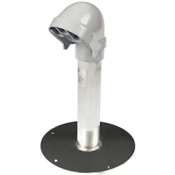
Menzies Electrical Roof Flashing
- Manufacturer
- Portals Plus
- Product
- Menzies Electrical Roof Flashing
- Status
- Current
- Market
- United States
- Latest file date
- April 2, 2016
- Last verified
- October 14, 2026
Overview
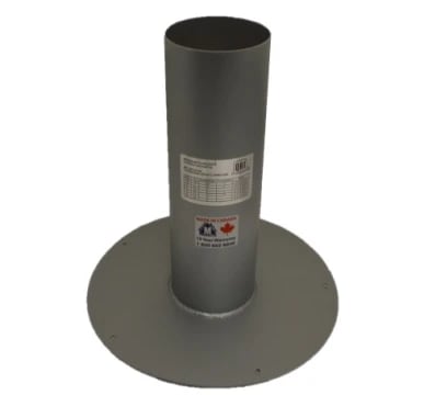
Menzies Electrical Roof Flashing carries electric cable through a roof deck. It is an aluminum stack pipe welded to a roof flange and topped with an electrical head, sold under the Menzies name by Portals Plus. It is made in 2 in. (51mm) and 3 in. (76mm) sizes for electrical conduits and is available for electrical and solar applications.
Two versions are covered on this page. The standard Menzies Electrical Roof Flashing has an aluminum flange for securing to the roof deck. Menzies Electrical Roof Flashing TPO has a TPO-coated flange and is the Menzies TPO Direct Weld version, made for installation on TPO roofing systems. Both versions share the same two sizes, the same stack and the same head design.
The standard flashing can also be made pitched for a steep roof. The pitch must be specified when it is ordered.
Sizes, weights and part numbers
The 2 in. size uses a 1 1/2 in. (38mm) plumbing stack. The 3 in. size uses a 3 1/2 in. (88mm) special pipe and carries a massive head, built for multiple usage. On the TPO version the 3 in. head fits multiple heavier conduit.
- 2 in. (51mm): 1.70 lbs, part number 600-1530 (standard) and 600-1530TPO (TPO).
- 3 in. (76mm): 6.45 lbs, part number 600-1550 (standard) and 600-1550TPO (TPO).
The TPO part numbers add the suffix TPO to the standard number; the weights are the same for both versions.
Data sheets and technical documents
Current files
Archived files
No older reviewed revisions are archived for this product yet.
Dimensions
Both sizes have a 4 in. (102mm) roof flange made of heavy duty aluminum for securing to the roof deck, with the pipe welded to the flange.
- 2 in. TPO: 16.5 in. overall height, with a 12 in. aluminum pipe below the entrance head assembly and the electrical head above it.
- 3 in. TPO: a 3 1/2 in. O.D. x 18 in. aluminum pipe welded to a flange with 12 in. by 12 in. outer dimensions, topped by the electrical head.
Drawings are dated 4/2/16 and carry the Menzies Metal Products title block. The 2 in. drawing is part 600-1530TPO and the 3 in. drawing is part 600-1550TPO.
Materials and construction
The stack is aluminum pipe welded to a heavy duty aluminum flange. The head is a two-part plastic assembly: a bottom portion that stays on the stack and a top portion that snaps onto it. On the 2 in. TPO version the entrance head assembly sits on the pipe with the electrical head above it.
On the TPO version the flange is coated with TPO, which lets the flange be welded directly to a TPO membrane. This is the Menzies TPO Direct Weld, made for fast installation on TPO roofing systems. The standard version is also available in the Menzies TPO Direct Weld form.
Listings and standards
Both versions are listed to meet Canadian and U.S. standards.
- Standard version: the roof flashing is QAI listed and the weatherhead is UL listed. The roof flashing meets CSA B272 and IAPMO PS 64. The weatherhead meets UL 514B.
- TPO version: the stack and base are QAI listed and the cap is UL listed. The flashing base and stack meet CSA B272 and IAPMO PS 64. The cap meets UL 514B.
On the TPO version the stack meets CSA standards and the electrical head meets UL and CSA standards.
Installation sequence
Installation instructions cover the 2 in. and 3 in. electrical stack roof flashing together, dated 01242014. The steps run in this order:
- Safety first; make certain that the wiring is not "hot".
- Be certain that the hole in the roof deck is sized appropriately with no sharp edges. The hole cannot exceed the diameter of the electrical stack pipe.
- Cut an appropriate sized hole through both materials over the hole in the roof deck. On an existing roof, remove debris or materials that may prevent the electrical stack flange from laying flush on the deck.
- Remove the top portion of the plastic head from the electrical stack. The bottom portion of the head stays attached to the stack.
- Position the electrical stack head based on requirements. A membrane compatible adhesive (for single ply) adheres the underside of the flange to the roof deck. Lower the flashing onto the deck and secure it with a minimum of 5 round head fasteners screwed into a solid substrate. Fastening evenly spaced, 1 in. from the edge of the flange, is optimal.
- Run the wiring up through the electrical stack, leaving at least 18 in. of excess wiring above the top of the stack. Fold the wiring into a tight radius, conforming to the shape of the bottom of the plastic head.
- Punch out the appropriate hole in the bottom of the head and feed the wires through the hole.
- Snap the top of the electrical head securely onto the bottom of the electrical head.
- Follow the roofing system manufacturer's installation instructions to install and flash the roofing membrane to the flange of the electrical stack.
- Adhere to installation requirements as determined by the regulatory authorities of the region.