Expansion Joint Cover
- Manufacturer
- Portals Plus
- Product
- Expansion Joint Cover
- Status
- Current
- Market
- United States
- Last verified
- October 14, 2026
Overview
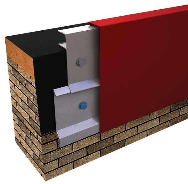
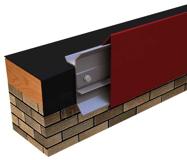
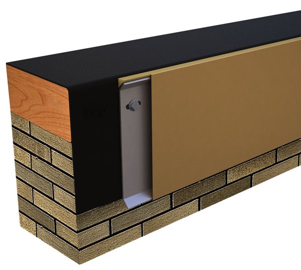
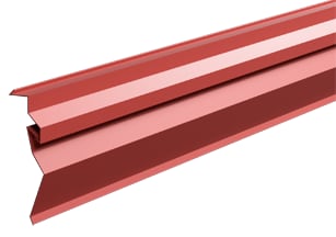
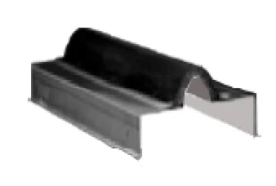
The Portals Plus Expansion Joint Cover is a factory-fabricated weather cover for structural expansion joints in roof decks. A flexible bellow spans the joint opening and is double-locked along both long edges to metal flanges that attach to the roof or curb on each side. A 3/8-inch layer of closed-cell flexible foam is laminated to the bellow cover; the foam insulates the bellow and allows for movement at the joint.
Three versions are offered: Curb Flange, Combination Flange and Straight Flange. The Curb Flange cover is built for curb applications, the Straight Flange cover for flat flange-to-flange applications, and the Combination Flange cover is the unit used with the curb and straight flange arrangements at walls. Covers are made for curb-to-curb, curb-to-wall, roof-to-roof and roof-to-wall conditions.
Metal flanges are available in galvanized steel, copper, stainless steel and aluminum, and bellows come in 4, 5, 6, 8, 10 and 12 inch widths. The cover is one of the joint-closure details used on low-slope roof assemblies where a structural expansion joint crosses the roof deck.
Roof expansion joints are called for when structural alterations or additions are made to an existing building, when the building length exceeds 200 feet, when the deck material changes (for example from poured concrete to steel), when a T, U or L-shaped structure is built, and when the direction of the structural framing changes.
Curb, combination and straight flange versions
The three versions share the same bellow construction and differ in the flange and in how the cover is supplied.
- Curb Flange: the galvanized, aluminum or stainless steel flanges are fabricated with an integral counterflashing and drip edge at the bottom for all curb applications. At walls, the standard combination curb and straight flange units are used. Covers are packaged in 10-foot pieces, 10 per carton for 4, 5, 6 and 8 inch bellows and 5 per carton for 10 and 12 inch bellows.
- Combination Flange: made for the same curb and wall conditions, with part numbers in galvanized, aluminum, stainless steel and copper across the 4 to 12 inch bellow widths. Packaged in 10-foot pieces, 10 per carton for 4 to 8 inch bellows and 5 per carton for 10 and 12 inch bellows.
- Straight Flange: straight flanges on both long edges. Galvanized, stainless steel and copper covers with 4, 5, 6 and 8 inch bellows come as one 50-foot coil per carton. Aluminum covers with 4 to 8 inch bellows come as 10 ten-foot pieces. All 10 and 12 inch bellows come as 5 ten-foot pieces.
Copper flanges are part of the Curb Flange, Combination Flange and Straight Flange part lists alongside galvanized, aluminum and stainless steel. The 10 and 12 inch bellow widths are special order only on the Curb Flange version.
Data sheets and technical documents
Current files
Archived files
No older reviewed revisions are archived for this product yet.
Bellow and foam construction
The bellow is a 3-ply, polyester scrim reinforced EPDM (ethylene propylene diene monomer) with a laminated closed-cell foam backing. Its nominal thickness is 0.045 inch (45 mils). The Combination Flange text names a reinforced Hypalon bellow, while its part numbers carry EPDM bellows.
Bellow physical properties:
- Weight: .31 lbf/ft2 (ASTM D 751).
- Tear strength: 60 lbf (267 N) (ASTM D 751).
- Breaking strength: 240 lbf (1068 N) (ASTM D 751).
- Elongation at fabric break: 15 percent in both directions (grab method).
- Ozone resistance: no cracks (ASTM D 1149).
- Heat aging: 240 degrees F for 28 days (ASTM D 573).
- Weather resistance: ASTM D 518, pass.
- Service temperature in air: maximum +248 degrees F (120 degrees C), minimum -129 degrees F (-54 degrees C).
The foam is 1/8 inch narrower than the nominal bellow width. It is 3/8 inch thick for bellow widths from 4 to 8 inches and 5/8 inch thick for 10 and 12 inch bellows.
Flange metals and dimensions
Metal flanges are 3-3/4 inches wide in every metal. Flange thickness depends on the metal:
- Galvanized steel: .018 inch (28 gauge).
- Copper: .021 inch (16 oz.).
- Stainless steel: .015 inch (28 gauge).
- Aluminum: .032 inch (22 gauge).
The bellow is double-locked to the flange along both long edges, a connection that forms the weathertight seam between metal and bellow.
The bellow selection chart sets the joint opening each bellow width suits. The curb-to-curb, curb-to-wall, roof-to-roof and roof-to-wall figures are the "X" dimension across the joint, and the vertical figure is the "Y" dimension up the wall:
- 4 inch bellow: curb-to-curb 6 in., curb-to-wall 2 in., roof-to-roof 2 in., roof-to-wall 2 in., vertical 6 in.
- 5 inch bellow: 7 in., 3 in., 3 in., 3 in., vertical 7 in.
- 6 inch bellow: 8 in., 4 in., 4 in., 4 in., vertical 8 in.
- 8 inch bellow: 9 in., 5 in., 5 in., 5 in., vertical 9 in.
- 10 inch bellow: 10 in., 6 in., 6 in., 6 in., vertical 10 in.
- 12 inch bellow: 12 in., 7 in., 8 in., 7 in., vertical 12 in.
Fittings, splices and accessories
Corners, tees, crossovers, closures and end terminations are factory-made by Portals Plus to suit the conditions on the roof. Corners, crossovers and tees are offered for the Curb Flange and Straight Flange versions in galvanized, aluminum, stainless steel and copper, in 4 to 12 inch bellow widths, and each is packaged one piece per carton.
Units are installed in the longest continuous lengths possible, and every splice is made with the Portals Plus standard splice kit. The self-sealing splice cover, wood roller, metal tool, primer and caulking supplied for the splice are the materials used for it. Installation and attachment follow the Portals Plus instructions and the roofing membrane manufacturer's recommendations.
The covers are used with asphalt, coal tar bitumen, modified bitumen, EPDM, TPO, PVC and Hypalon roofing, and with most other types.
Curb flange installation
The curb flange instructions are numbered Step 1 and Step 2.
- Step 1: all necessary materials are checked as on hand before starting.
- Step 2: all crossovers, tees and corners are installed first. Flanges are trimmed to leave a 1/2-inch space between each joint, with the bellows butted. Mastic or adhesive is held back at all joints. Straight runs follow with the same space in the flanges and the same butting of the bellows.
Curb-to-curb installations use these maximum curb sizes: 4 inch bellow 6 in., 5 inch 7 in., 6 inch 8 in., 8 inch 9 in., 10 inch 10 in., 12 inch 12 in. Curb-to-wall installations use these maximums: 4 inch bellow 4 in., 5 inch 5 in., 6 inch 6 in., 8 inch 7 in., 10 inch 8 in., 12 inch 9 in.
Fastening is by the nails provided, at 8 inches on center on both sides, with the first nail no more than 3-1/2 inches from the end of the metal. Mastic or water cut-off mastic is applied to suit the roof flashing material and held back at all joints. At a wall, counterflashing is not included, and the upper flange is installed high enough for the bellow to shed water.
At gravel stop and gutter terminations, the top of the curb slopes down to the perimeter nailer. Before the metal is bent at the edge, the foam insulation is slit and removed from the bellow, the extra metal is fished in and the flanges are soldered to the gravel stop. Where a gutter occurs, the expansion joint cover laps over the gravel stop into the gutter.
Joint splicing sequence
Joint splicing has three steps. In cold weather the splice covers are kept warm and pliable before starting.
- Step 1: the surfaces around the joint are cleaned and dried, and the metal flanges 4 inches on each side of the joint are cleaned with detergent or mild solvent if an oily film is present. Splicing primer is brushed on the bellows and both metal flanges, out 4 inches on each side of the butt joint, at 1 to 1-1/2 mils dry thickness. The primer is glossy when first applied and dries to a dull appearance in 15 minutes. A primed joint is not left exposed more than 1 hour.
- Step 2: the release paper on the self-sealing splice cover is peeled halfway from one end and creased. The cover is centered over the butt joint, rolled onto the bellow with the wood roller to remove air bubbles, and forced into the junction of bellow and metal flange with the metal tool, without stretching the cover. The release paper is then peeled from the remaining half and the second side is installed the same way.
- Step 3: a bead of caulking is applied from the edge of the splice cover, extending about 1 inch along the crimp, at each of the four places where the splice cover crosses the crimp.