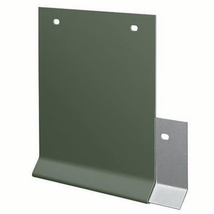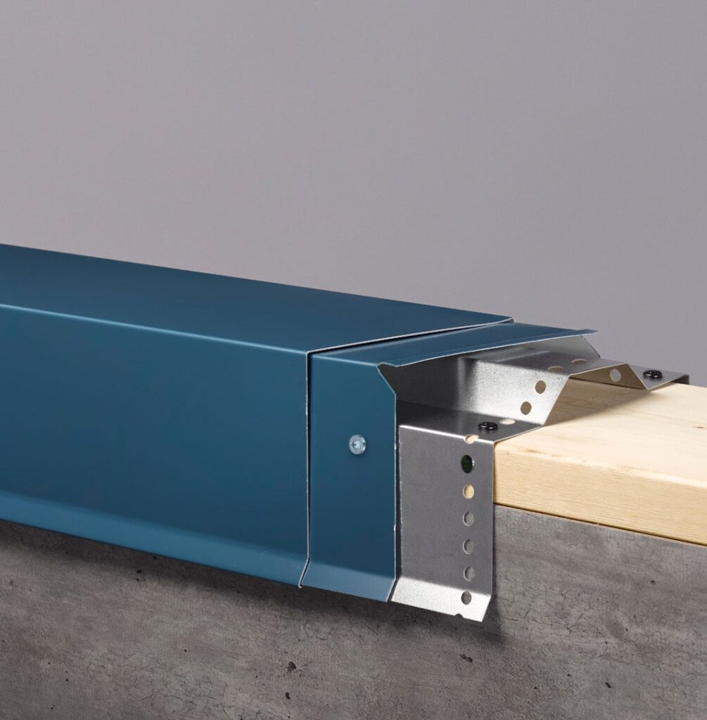
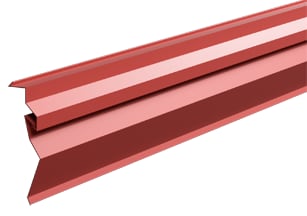
Drive-Lock Reglet
- Manufacturer
- Hickman Edge Systems
- Product
- Drive-Lock Reglet
- Status
- Current
- Market
- United States
- Latest revision
- B
- Latest file date
- April 27, 2022
- Last verified
- October 14, 2026
Overview
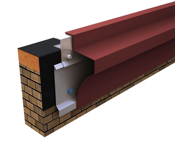
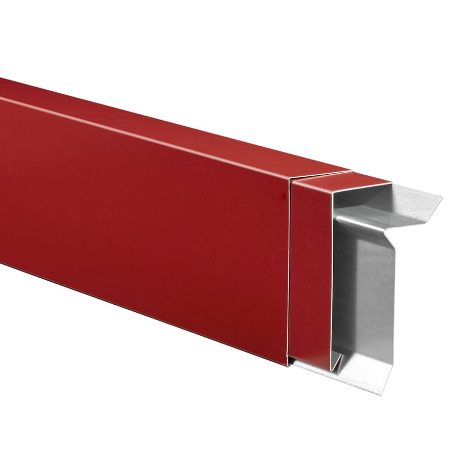
The Drive-Lock Reglet is a two-piece counterflashing system from Hickman Edge Systems. A reglet receiver is installed first, and the counterflashing is hooked onto it and rotated downward until it snaps into the receiver. The assembly provides a watertight termination at the leading edge of the roofing material, and the two pieces can be disassembled for roof repairs.
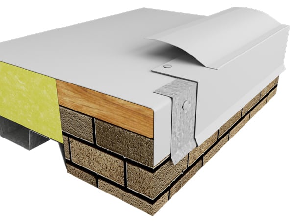
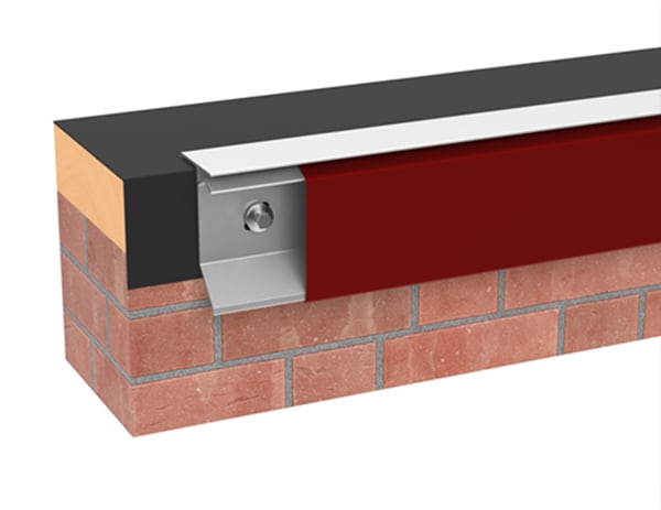
Two versions are listed. The In-Wall Drive-Lock Reglet version has its receiver set into a saw cut or mortar joint in the wall. The Drive-Lock Reglet version is the surface version: its receiver is mounted on the face of the wall and has slotted holes for fasteners. Both belong to the Roof Edge Accessories line.
The roof flashing and any cant strip are supplied by others, as in a termination detail of the kind used on low-slope roof assemblies.
Sizes and part numbers
Standard sizes are 3.5 in., 4 in. and 5 in. The size is the H dimension, called the face height on the in-wall version. Part numbers by version:
- In-Wall Drive-Lock Reglet version: CFR2-350R for 3.5 in., CFR2-400R for 4 in. and CFR2-500R for 5 in.
- Drive-Lock Reglet version: CFW2-350R for 3.5 in., CFW2-400R for 4 in. and CFW2-500R for 5 in.
Data sheets and technical documents
Current files
Archived files
No older reviewed revisions are archived for this product yet.
Lengths, joints and fasteners
Both versions are provided in 12-ft. lengths with pre-notched lap joints. The lap at each joint is 3 in., formed at the factory-notched end of the receiver and by a 3-in. notch in the counterflashing. The Drive-Lock Reglet version has pre-punched slotted holes measuring 9/32 in. by 3/8 in., spaced 12 in. on center, which allow thermal movement of the materials and set the fastener placement and spacing.
No fasteners are provided with either version. The non-curing sealant is supplied by others, and so are the fasteners for the slotted holes of the Drive-Lock Reglet version, which are placed 12 in. on center through the pre-punched slots.
Materials, finishes and colors
The reglet is made in 24-gauge or 22-gauge galvanized steel, or in .040-in. or .050-in. aluminum. Color and finish are named on the order form. Both the receiver and the counterflashing leave the factory with a protective film.
Across the Roof Edge Accessories line, which includes both reglets, ten express colors are offered: Dark Bronze, Bone White, Cityscape, Almond, Medium Bronze, Sandstone, Sierra Tan, Slate Gray, Stone White and Clear Anodized. Mill finish and custom colors are also available. For Drive-Lock Reglet, coil-coated standard colors carry a 30-year Kynar 500 finish warranty.
Installation of the in-wall version
Installation of the in-wall version follows four steps:
- The reglet receiver is installed into a 1-in. deep saw cut or mortar joint. The saw cut is cut true and level, a minimum of 7 in. above the high point of the cant strip if one is used. Receivers are installed from right to left, with the ends lapped 3 in. at the factory-notched end. The protective film is removed immediately.
- The protective film is removed from the counterflashing, which is hooked onto the receiver and rotated downward into place. Receiver joints and counterflashing joints are staggered.
- Each following counterflashing piece is hooked onto the receiver, slid 3 in. over the previously installed piece at the lap joint, and rotated downward into place. A 3-in. notch forms the lap.
- A continuous bead of high-grade architectural sealant, supplied by others, is applied in the caulk cup of the reglet to complete the installation.
Installation of the surface version
Installation of the Drive-Lock Reglet surface version follows four steps. The reglet receiver sits on the wall above the roof flashing and cant strip, with the roof flashing, cant strip and fasteners all supplied by others.
- Step 1, Reglet Receiver: The wall-mounted receiver is installed true and level, a minimum of 7 in. above the high point of the cant strip if one is used. Installation runs from right to left. The receiver is fastened with appropriate fasteners, supplied by others, through the pre-punched slots 12 in. on center. The ends of the reglet are lapped 3 in. at the factory-notched end. The protective film is removed immediately.
- Step 2, Counterflashing: The protective film is removed before the counterflashing is installed. The counterflashing is hooked onto the receiver (Fig. A) and rotated downward into place (Fig. B). Reglet receiver joints and counterflashing joints are staggered accordingly.
- Step 3, Counterflashing: The protective film is removed, and the counterflashing is hooked onto the receiver (Fig. C). It is slid 3 in. at the lap joint over the previously installed piece, then rotated downward into place as in Step 2. A 3-in. notch forms the lap.
- Step 4, Completion: A continuous bead of high grade architectural sealant, supplied by others, is applied in the caulk cup of the reglet to complete the installation.
In the typical installation section, the sealant sits at the top of the receiver, the fasteners pass through the pre-slotted holes 12 in. on center, and the counterflashing hangs below the receiver. The dimension from the high point of the cant strip up to the receiver is 7 in. minimum.
Other versions in the accessories line
The Roof Edge Accessories line also lists In Wall Surface Mount, Surface Mount and Thru-Wall versions, together with the Snap-on Reglet and Snap-on EX Reglet.
Warranty
The Drive-Lock Reglet carries a 5-year workmanship warranty. On Drive-Lock Reglet, the warranty covers replacement or repair of products that are defective in material or workmanship.