Creative Design Cornice Fascia
- Manufacturer
- Metal-Era
- Product
- Creative Design Cornice Fascia
- Status
- Current
- Market
- United States
- Latest file date
- November 13, 2017
- Last verified
- October 14, 2026
Overview
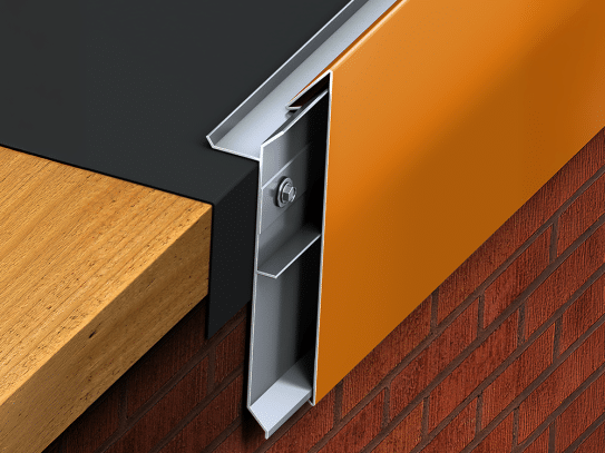
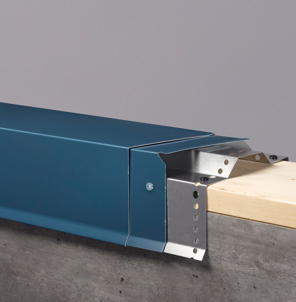
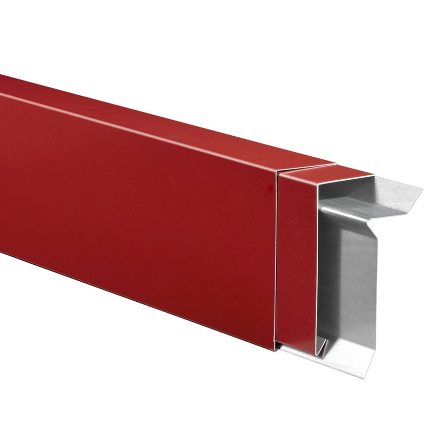
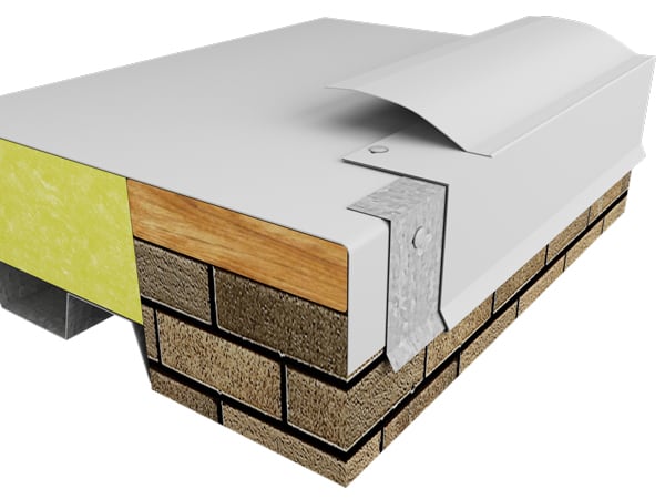
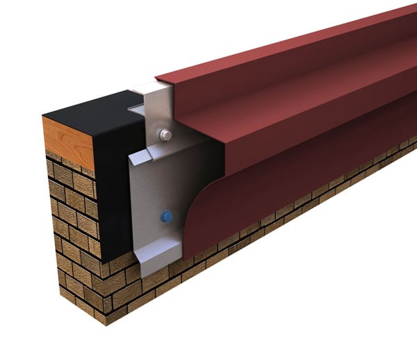
Creative Design Cornice Fascia is a roof-edge fascia from Metal-Era's Creative Design Series. Its cornice profile gives the building edge a shaped face, and the cover is held by a patented, extruded aluminum anchor bar that terminates the roofing membrane. Covers are supplied in 4-ft. lengths with pre-punched, slotted fastening holes, and the system is non-penetrating, so no stripping-in or heat welding is part of the edge detail.
The product is made in two versions. The single-ply version is for fully adhered or mechanically attached single-ply roofs, and the built-up or modified version is for BUR or modified bitumen roofs. Both share the same face heights, cover materials, finishes and warranty options, and they differ in the membrane detail at the anchor bar and in their installation instructions. Within the Creative Design Series the cornice is one of three fascia profiles; the other two are the bullnose and the shadow line.
The fascia is one of the perimeter metal components used to finish low-slope roof assemblies, where the membrane is carried over the edge and the metal covers the termination. Factory-fabricated miters, endcaps and accessories come with the system, so corners are not formed in the field.
Versions and how they differ
The single-ply and built-up or modified versions use matching face heights and the same cover, cleat and splice-plate components. The differences are in the product identification numbers and in the membrane detail at the edge.
- Single-ply version (fully adhered or mechanically attached): product IDs AEF-CS85, AEF-CS100, AEF-CS115 and AEF-CS130. Non-curing sealant, supplied by others, is placed between the anchor bar and the roofing membrane.
- Built-up or modified version: product IDs AEFM-CS85, AEFM-CS100, AEFM-CS115 and AEFM-CS130. The edge detail shows approved mastic or sealant and a flashing strip under the anchor bar.
The single-ply version is installed to Metal-Era installation instructions Dwg. # 11110-5229, and the built-up or modified version to Dwg. # 11110-5230.
Data sheets and technical documents
Current files
Archived files
No older reviewed revisions are archived for this product yet.
Face heights and cover materials
Four face heights are made, to suit different nailer and coverage requirements:
- 8 1/2 in. (216 mm), IDs AEF-CS85 and AEFM-CS85
- 10 in. (251 mm), IDs AEF-CS100 and AEFM-CS100
- 11 1/2 in. (292 mm), IDs AEF-CS115 and AEFM-CS115
- 13 in. (330 mm), IDs AEF-CS130 and AEFM-CS130
Covers are formed from aluminum in two thicknesses, .050 in. (1.27 mm) and .063 in. (1.60 mm). A steel cover can also be selected, in 22-gauge steel. Other materials can be written in on the print approval form, and specially fabricated products are available for the needs of a particular project.
The print approval form covers face height, material, color, finish and the quantities of 12-ft. lineal feet, outside and inside 90° miters, and right and left endcaps. CAD drawings are published for each face height in both versions.
Anchor bar, cleat, splice plates and fasteners
The anchor bar is extruded aluminum in 12-ft. lengths. It holds the roofing membrane and carries the cover, and the bar can be removed, cleaned and reinstalled when the roof is replaced without loss of strength or appearance. A continuous cleat of 20-gauge galvanized steel is hooked to the lower edge of the cover. The anchor bar design is covered by U.S. Patent # 7,451,572.
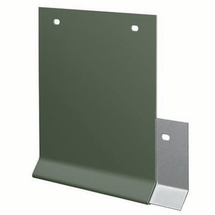
Joints between 4-ft. cover sections are backed by 3 1/2-in. splice plates at every joint. The splice plates are concealed and interlock, so they do not migrate under the panels, and no cover plate or lap joint shows at the seam.
Metal-Era provides the fasteners and the anchor bar splice plates with the product, and the sealant is by others:
- #10 x 2-in. stainless-steel fasteners through the anchor bar, 12 in. on center.
- 1/4 x 1 1/4-in. masonry or wood fasteners through the cleat, 24 in. on center.
Fastening holes are pre-punched and slotted so the metal can move with temperature changes and the fasteners land at the correct spacing.
Finishes and colors
Standard colors are coil-coated with Kynar 500 and include a 30-year Kynar 500 finish warranty. Custom post-coated Kynar 500 colors include a 10-year finish warranty, and a 20-year finish warranty is available on request. Anodized finishes carry a 5-year warranty; coil anodizing has no warranty, and post-coat Class 1 batch anodizing can be raised from 5 to 10 years for an upcharge. All colors are also available in mill finish.
For Creative Design Cornice Fascia, ten express colors are offered: Medium Bronze, Sandstone, Sierra Tan, Slate Gray, Stone White, Dark Bronze, Bone White, Cityscape, Almond and Clear Anodized. A protective plastic film covers each cover and is removed before the cover is installed.
Miters, endcaps and the fascia extender
Outside and inside 90° miters, right and left endcaps, spillouts and scuppers are factory fabricated, which removes field fabrication of corners. Non-90° miters use a separate print approval, #11010-1103, and a non-90° angle measurement worksheet is published for taking the angle at the wall.
A fascia extender is made for both versions in two forms, a splice plate version and a lap joint version, each with its own installation instructions, plus print approvals for extenders without and with an offset. The extender with offset has pre-slotted holes 12 in. on center and a continuous 22-gauge galvanized cleat that is included. It is made in 24-gauge or 22-gauge galvanized steel and in .040-in., .050-in. or .063-in. aluminum, and the .050-in. and .063-in. aluminum extenders come with 3 1/2-in. wide concealed splice plates because of the material thickness. Welded miters and accessories are an option.
The lap joint extender is installed with miters first. The continuous cleat is fastened true and level at 12 in. on center, the drip edge of each panel is hooked onto the cleat and fastened at 12 in. on center, and panels run right to left as seen from the rooftop with a 1-in. lap at each joint at the notch provided.
Installation of the single-ply version
The single-ply installation instructions run in seven numbered steps:
- Roof Membrane. The membrane is positioned over the roof edge and down the outside face of the wall, covering the treated wood nailer or nailers completely, with 1/2 in. of excess membrane. The outside edge of the nailers (minimum 2 x 4) is aligned flush with, or extends slightly past, the outermost edge of the wall.
- Miter and Scupper Anchor Bar (Preparation). Miters and scuppers are laid on the deck with the outside face down and the aluminum anchor bar is cleaned. A heavy 3/8-in. bead of non-curing sealant goes along the right-angle intersection of the deck flange and the back of the anchor bar, along the full length of each miter anchor bar.
- Anchor Bar Splice Plates. Non-curing sealant is applied to each plate as in step 2. Eye protection is worn, fasteners are not over-driven, and a 600-800 rpm electric drill with a depth-sensing nosepiece is the recommended tool; an impact tool is not used.
- Miter Bar and Miter Cleat Installation. The miter cleat is hooked to the miter bar and the ends are flushed. The membrane is folded at the corners and the miter assembly is set with one anchor bar splice plate under each end of the bar, snug to the ends. The miter bar takes 2-in. hex head stainless steel fasteners and the miter cleat takes 1 1/4-in. hex head corrosion-resistant fasteners. Spillouts and scuppers follow, with sealant, fasteners and anchor bar plates.
- Anchor Bar and Cleat Installation. The anchor cleat is hooked to the anchor bar. Sections of 12-ft. anchor bar and cleat with sealant are positioned over the overlapping splice plate, leaving a 1/2-in. space between anchor bars. The anchor bar is fastened 12 in. on center through the slotted holes with 2-in. fasteners and the cleat 24 in. on center with 1 1/4-in. fasteners. Sections are field cut as needed.
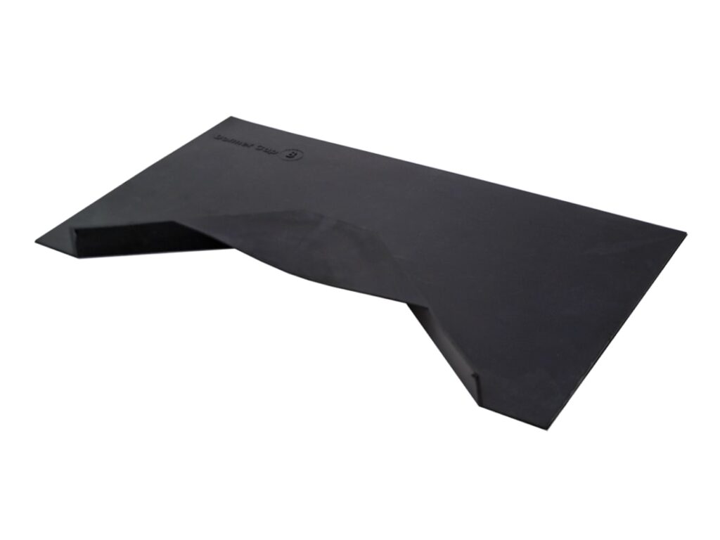
- Fascia Miter Covers. Miter covers go on first, with one splice plate under each end. Each cover engages the anchor cleat and rotates up and over the anchor bar miter until it is engaged along the full length of the bar.
- Fascia Covers. The 4-ft. covers are installed with a 3/8-in. gap between sections and one splice plate under the far end of each. The lower edge of the cover is hooked onto the anchor cleat and rotated up and over the anchor bar until engaged along its full length. Covers are field cut with a fine-tooth hacksaw where needed.
The protective plastic film is removed before each fascia section is installed.
Wind warranty
A Creative Design 20-year, 120 mph wind warranty is available on orders that call for it. It provides a maximum of 20 years and 120 mph coverage for the repair or replacement of any portion of the roof edge system that fails because of a defect in materials supplied by Metal-Era. The finish warranties described above are separate. The cornice version carries no ANSI/SPRI/FM 4435/ES-1 testing (N/A).