One Edge CF Fascia
- Manufacturer
- Metal-Era
- Product
- One Edge CF Fascia
- Status
- Current
- Market
- United States
- Latest revision
- D
- Latest file date
- June 17, 2024
- Last verified
- October 14, 2026
Overview
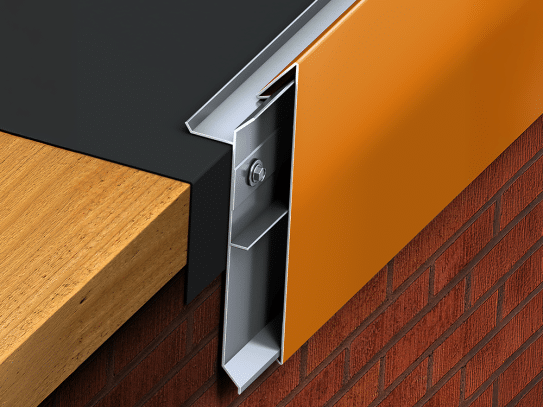
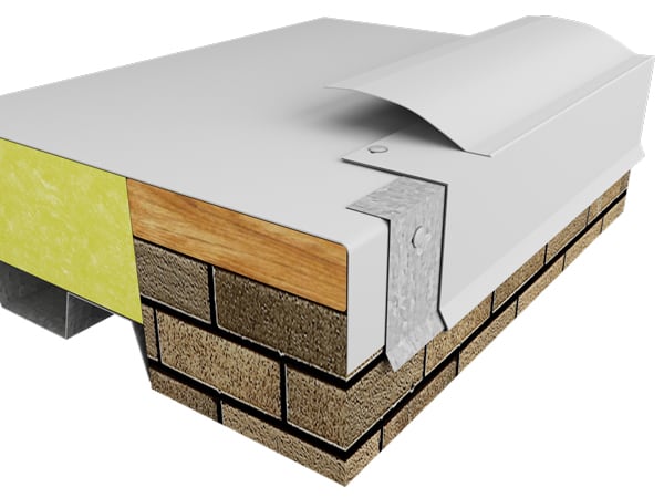
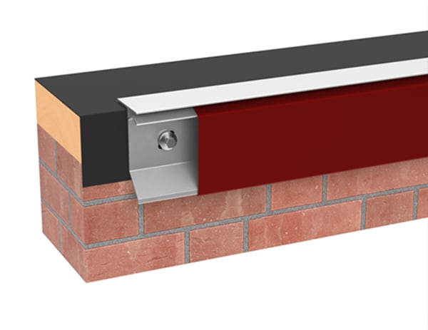
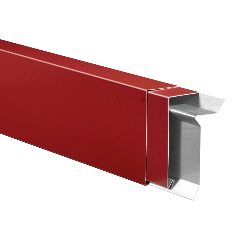
One Edge CF Fascia is a snap-on metal fascia from Metal-Era's Edge Systems One family, made for the edge of a fully adhered or mechanically attached single-ply roof. A 20-gauge retainer is fastened to the blocking at the roof edge over the membrane, and the formed fascia cap hooks onto the retainer and snaps into place. Both the cap and the retainer are formed in 12 ft. lengths, and the fastening holes are pre-punched.
The fascia is one of the perimeter metal components used to finish single-ply low-slope roof assemblies. The CF version is the one with the retainer; the same Edge Systems One line also includes One Edge Fascia and One Edge Extended Fascia, which are listed with spring clips and a single-ply or built-up and modified bitumen version each.
Splice plates and fasteners are included with the product. Factory-fabricated accessories cover corners, ends, scuppers and radius work, so the fascia is not formed in the field.
Face heights and nailer coverage
Seven standard face heights are made, each tied to the number of wood nailers it covers. The X dimension is the vertical distance used to locate the lower fastener rows on the blocking.
- TE-350: 3 1/2 in. face height, X dimension 2 3/4 in., 1 nailer.
- TE-475: 4 3/4 in. face height, X dimension 4 in., 2 nailers.
- TE-625: 6 1/4 in. face height, X dimension 5 1/2 in., 3 nailers.
- TE-775: 7 3/4 in. face height, X dimension 7 in., 4 nailers.
- TE-925: 9 1/4 in. face height, X dimension 8 1/2 in., 5 nailers.
- TE-1075: 10 3/4 in. face height, X dimension 10 in., 6 nailers.
- TE-1225: 12 1/4 in. face height, X dimension 11 1/2 in., 7 nailers.
The face height runs from a 3 1/2 in. minimum to a 12 1/4 in. maximum.
Data sheets and technical documents
Current files
Archived files
No older reviewed revisions are archived for this product yet.
Cover materials and finishes
The cap is made in four materials: 22-gauge galvanized steel, 24-gauge galvanized steel, .040 in. aluminum and .050 in. aluminum. Material is tied to face height:
- The 3 1/2 in. face height is available only in 24-gauge galvanized steel and .040 in. aluminum.
- Face heights of 9 1/4 in. and over are available only in 22-gauge galvanized steel or .050 in. aluminum.
For One Edge CF Fascia, standard colors are coil-coated and carry a 30-year Kynar 500 finish warranty. On One Edge CF Fascia, custom post-coated Kynar 500 colors come with a 10-year Kynar 500 finish warranty, and a 20-year warranty is available on request. Anodized finishes are also offered: coil anodized finishing has no warranty, while post-coat Class 1 batch anodized finishing has a 5-year warranty with an option to raise it to 10 years for an upcharge. A mill finish is available as well.
For One Edge CF Fascia, ten express colors are offered: Medium Bronze, Sandstone, Sierra Tan, Slate Gray, Stone White, Dark Bronze, Bone White, Cityscape, Almond and Clear Anodized.
Retainer, fastening and splice plates
The retainer is 20-gauge galvanized and is formed in 12 ft. lengths. A continuous bead of the roofing manufacturer's non-curing sealant, supplied by others, goes on the underside of the retainer before it is set over the membrane. The membrane is attached to the metal in accordance with the membrane manufacturer's specifications.
Fasteners are provided and are spaced at 12 in. on center, starting 6 in. from the ends. The number of rows depends on the face height:
- First row, required for every face height.
- Second row, required for 6 1/4 in., 7 3/4 in. and 9 1/4 in. face heights.
- Third row, required for 10 3/4 in. and 12 1/4 in. face heights.
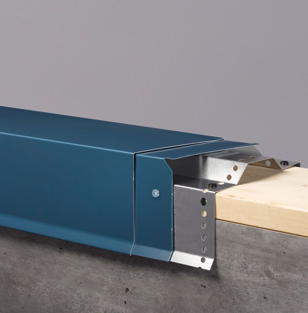
Joints between fascia lengths are covered by concealed splice plates 4 in. wide. The plates allow for thermal movement of the metal and make a watertight seal at every joint. Fastening holes are slotted to allow the same movement and to place fasteners at the correct spacing. On masonry, a 3/16 in. pilot hole is called for.
Blocking is supplied by others. The substrate is named on the order as wood, masonry or metal; where none is given, wood fasteners are provided.
Testing and approvals
The fascia is tested to ANSI/SPRI/FM 4435/ES-1, the roof-edge wind test referenced by the International Building Code, with test pressures up to 381 psf. The maximum tested face height is 9 1/4 in.
The product is FM Approved for wind uplift protection and holds a Miami-Dade approval, 23-0912.08 (12/11/28), for the High Velocity Hurricane Zone of the Florida Building Code.
A 20-year, 120 mph Edge Systems One wind warranty is available on orders that call for it. It covers repair or replacement of any portion of the roof edge system that has failed because of a defect in Metal-Era supplied materials, up to 20 years and 120 mph.
Miters, end pieces and scuppers
The standard shop-made pieces are right and left endcaps, right and left endwall flashings, 90 degree outside miters (cover only), 90 degree inside miters (cover only), downspout scuppers and spillout scuppers. Non-90 degree miters are covered by a separate print approval. Straight runs are ordered in lineal feet of 12 ft. lengths.
Radius fascia is ordered in lineal feet of 4 ft. lengths. The product cannot be installed on conditions smaller than a 5 ft. radius. Vaulted fascia is also installed, using intermittent straight clips, and the length of those clips can vary with the vault radius specified.
Inside corners use a two-piece miter, PC-1 and PC-2, with a splice placed in each side of the miter.
Installation sequence
The installation guide numbers the work as follows:
- Step 1, Consider Downspout Scuppers and Spillout Scupper Locations. Downspout scuppers go where downspouts will be located and are installed before the retainer; the retainer butts up to the sides of the scupper. Spillouts are installed along with the fascia lengths as required.
- Step 2, Installing Retainer. Apply a continuous bead of the roofing manufacturer's sealant to the bottom of the retainer, set it over the membrane as close to the corner as possible while allowing for the adjacent retainer, and fasten it to the substrate with the fasteners provided. Adjacent retainers are butted together. Masonry needs a pre-drilled pilot hole.
- Step 3, Installing Outside Fascia Miters. A splice goes in each side of the miter. The top flange of the miter hooks onto the top flange of the retainer, the fascia is rotated outward, and pressing down on the top flange snaps the bottom hook onto the bottom of the retainer.
- Step 4, Installing Inside Fascia Miters. PC-1 is hooked onto the retainer and snapped on, with its bent flange seated in the corner. PC-2 is installed the same way, overlapping the bent flange and the top of PC-1.
- Step 5, Installing Fascia End Caps and End Terms. Hook the top and press the top face downward to snap the piece into place.
- Step 6a, Installing Fascia Straight Lengths. A splice goes in the open end of the installed miter, and the fascia is hooked and pressed down. A 3/8 in. gap is left between fascia sections for thermal expansion, and a splice is required at every joint. Lengths are reviewed before cutting so that short sections do not end up beside full-length sections.
- Step 6b, Installing Fascia Radius Lengths, follows the same method with the 3/8 in. gap and a splice at every joint, over a notched radius retainer.
- Step 6c, Installing Fascia Vaulted Lengths. A clip is placed at each joint so that the cap overlaps it to the middle of the clip, and a further clip goes at the middle of each cap section, each secured through the pre-punched holes.
At every splice, the bottom of the splice is not hooked onto the retainer.
Scupper installation and installation notes
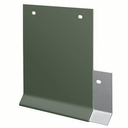
Downspout scuppers start with the scupper core, fastened to the wood nailer with a minimum of three ring shank nails. The retainer is butted to the core, membrane flashing strip is applied into the core as the membrane manufacturer requires, and the scupper face is then snapped on with a concealed splice at each end.
A spillout scupper is fastened to the wood nailer with a minimum of two ring shank nails and is installed before the retainer. The membrane is flashed into the spillout without leaving any sharp edges against it. The scupper face is made in two halves: the tabbed half slides under the other half and inside the formed drip of the non-tabbed side.
Two notes accompany the drawings. All metal parts are isolated from ACQ treated wood and other galvanically incompatible material with appropriate membrane material. Appliance attachments such as lightning rods, signs or antennae that penetrate the edge system, cause a galvanic reaction or otherwise compromise the roof edge system are eliminated or isolated, in line with ANSI/SPRI/FM 4435/ES-1, and lightning protection systems are not affixed directly to the fascia.