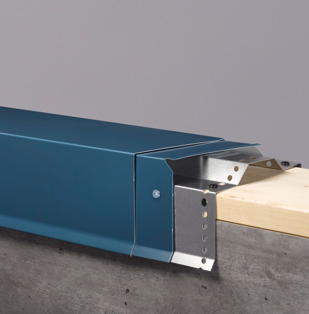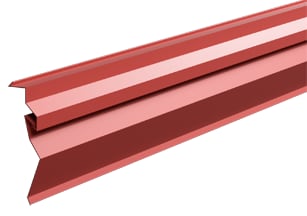
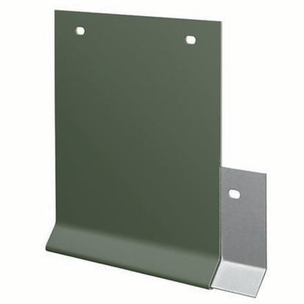
Extender and Extender with Offset
- Manufacturer
- Hickman Edge Systems
- Product
- Extender and Extender with Offset
- Status
- Current
- Market
- United States
- Latest revision
- A
- Latest file date
- September 21, 2022
- Last verified
- October 14, 2026
Overview
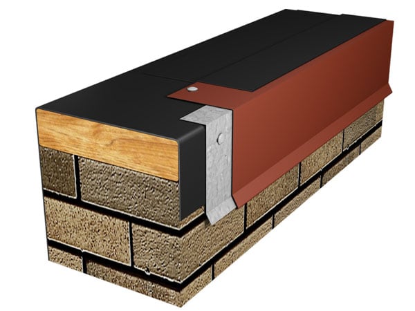
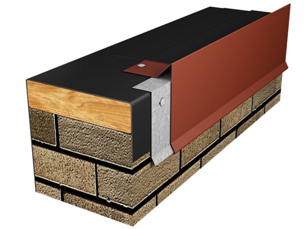
The Extender and the Extender with Offset are fascia extenders from Hickman Edge Systems. Each consists of a 24-gauge galvanized continuous cleat and a formed fascia extender, and both parts are made in 12-ft. lengths. The extender overlaps the fascia, coping, extender or trim above it by 1 1/2 in., and the order drawings for both versions are titled for non-standard height.
The two versions share the same published face range, cleat, splice, nailing and test pressure. The detail for both includes a roofing membrane, as in the roof edge details of low-slope roof assemblies.
One installation drawing, 64114-38181 Revision A, covers the Extender with and without offset. The date on the drawing is 9/21/22, and it carries the ANSI/SPRI/FM 4435/ES-1 TESTED mark.
Face heights, cleat and splice
Face height runs from 2 in. to 13 in. Testing covers face heights up to 8 in. The extender and the cleat are each formed in 12-ft. lengths.
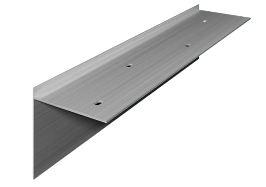
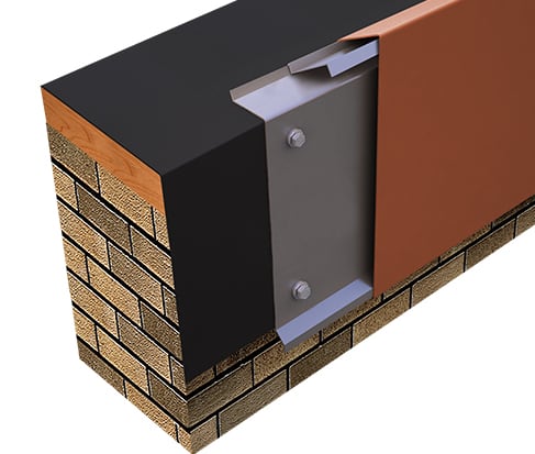
The cleat has a locator flange and pre-punched slotted holes 12 in. on center. Nails are provided at 12 in. on center. A concealed splice plate, 4 in. wide, joins the lengths. It keeps the color continuous at joints and prevents water infiltration at them. The order form asks for the substrate, which is wood, masonry or metal, and wood fasteners are provided when none is named.
Data sheets and technical documents
Current files
Archived files
No older reviewed revisions are archived for this product yet.
Components and fastening
Five parts make up both the Extender with Offset and the Extender without offset:
- A, the formed fascia cover.
- B, the concealed joint splice.
- C, the galvanized anchor cleat.
- D, the fastener, set at 12 in. on center and 6 in. from the ends through the pre-punched holes.
- E, the fascia, coping or extender above.
Fasteners at 12 in. on center are provided with the product. The extender hooks onto the cleat by its drip, which sits on the kick out of the cleat.
Materials, finishes and colors
The cleat is 24-gauge galvanized steel. The cover is made in 24-gauge or 22-gauge galvanized steel, or in .040-in., .050-in. or .063-in. aluminum. Color and finish are named on the order form.
The extenders come in ten express colors: Dark Bronze, Bone White, Cityscape, Almond, Medium Bronze, Sandstone, Sierra Tan, Slate Gray, Stone White and Clear Anodized. A mill finish and custom colors are also available. Coil-coated standard colors in the line are covered by a 30-year Kynar 500 finish warranty.
Wind testing, approvals and warranty
- Tested per ANSI/SPRI/FM 4435/ES-1 to comply with the International Building Code, with test pressures up to 107 psf in the horizontal direction.
- Factory Mutual approved for wind uplift protection; it carries the FM Approved mark.
- Miami-Dade approved to comply with the High Velocity Hurricane Zone of the Florida Building Code.
A 20-year, 120 MPH wind warranty is included with the Extender. Products in the Roof Edge Accessories line also come with a 5-year workmanship warranty.
Installation steps
Installation has five steps, in this order:
- Installing Anchor Cleat. The top edge of the anchor cleat is placed level on the wall face, pressed securely into position and secured through the pre-punched holes with the mechanical fasteners provided. At a miter, the cleat is fitted into the corner as required to keep a continuous anchor cleat line, then secured at a minimum of 6 in. in each direction from the corner, or closer at special conditions. A 1/8 in. gap is left between cleat sections for thermal movement.
- Installing Fascia Miters. The fascia miters and joint splices are located for the appropriate corners, and a joint splice is placed under each end of the miter sections. The miter is installed by hooking the drip of the fascia onto the kick out of the cleat and rotating it back until the fascia is flush with the wall face. It is fastened through the pre-punched holes with the mechanical fasteners provided.
- Installing Fascia End Caps and End Terms. The fascia is installed by hooking its drip onto the kick out of the cleat and rotating it back flush with the wall face, then fastened through the pre-punched holes with the mechanical fasteners provided.
- Installing Fascia Straight Lengths. A concealed joint splice is placed on the opposite end of the installed miter or end cap. The fascia is hooked by its drip onto the kick out of the cleat, rotated back flush with the wall face and fastened through the pre-punched holes with the mechanical fasteners provided. A 1/4 in. gap is left between fascia sections for thermal expansion. The lengths of all straight pieces are considered before cutting, to avoid short sections of fascia next to a full-length section. A joint splice goes at every joint.
- Installing Product Above. The product above the fascia is installed per its own manufacturer's installation instructions.
The outside corner and inside corner, the end cap, the end term, the fascia miter and the straight length each come with a joint splice.
Installation notes
- All metal parts are isolated from ACQ treated wood or other galvanically incompatible material with appropriate membrane material.
- Appliance attachments such as lightning rods, signs or antennae that penetrate the edge system, induce a galvanic reaction or otherwise compromise the effectiveness of the roof edge system are eliminated or isolated, per ANSI/SPRI/FM 4435/ES-1.
- Lightning protection systems must not be affixed directly to the product provided by Hickman Edge Systems.
Miters, endcaps and endwall flashings
Inside and outside miters and other accessories are available in standard lengths. The standard miter angle is 90°. Custom miters can be made, and non-90° miters have a separate print approval. Accessories are ordered as left and right endcaps, left and right endwall flashings, and inside and outside 90° miters. Miter legs are a nominal 14 3/8 in., and the endcaps and endwall flashings are drawn at a nominal 18 in.
Unless otherwise noted, miters and accessories are made with a non-penetrating quicklock joint and factory sealed watertight. Welded accessories are a surcharge item and need a minimum material thickness of .050 in.