One Edge Extended Fascia
- Manufacturer
- Metal-Era
- Product
- One Edge Extended Fascia
- Status
- Current
- Market
- United States
- Latest revision
- M
- Latest file date
- January 15, 2020
- Last verified
- October 14, 2026
Overview
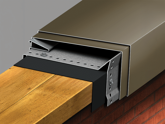
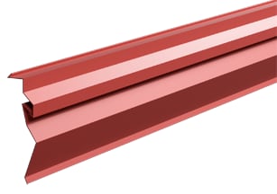
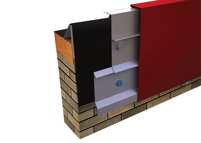
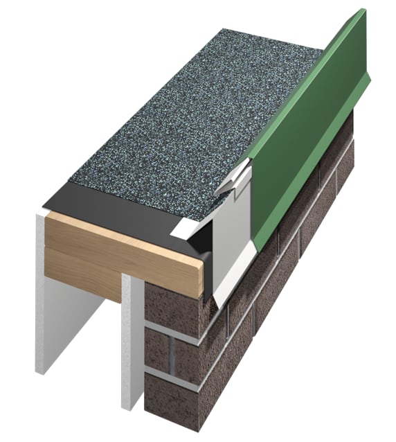
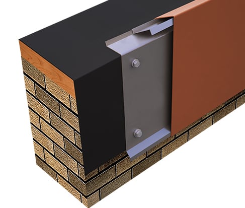
One Edge Extended Fascia is a snap-on metal fascia from Metal-Era's Edge Systems One family. A formed rail is fastened to the wall or nailer, stainless-steel spring clips sit on the rail, and the fascia cover presses down onto the rail by hand. The snap-on design eliminates the stripping used with other fascia products. Covers and rails are supplied in 12'-0" lengths with pre-punched holes, and the fastening holes are slotted to allow thermal movement of the materials and to place fasteners at the correct spacing.
There are two versions: One Edge Extended Fascia Single-Ply, for fully adhered or mechanically attached single-ply membranes, and One Edge Extended Fascia Built-Up or Modified, for built-up and modified bitumen roofs. Both are marked FM Approved on their print approvals and installation instructions, and the single-ply version is covered by U.S. Patent #5,927,023.
The fascia is meant as perimeter securement on roof designs where it is not installed in a waterline. Where the edge sits in a waterline or needs drainage over the edge, Metal-Era points to Anchor-Tite Canted Fascia or Anchor-Tite Drip Edge instead, depending on how much water is to be retained. The cover is one of the perimeter metal components that finish low-slope roof assemblies such as single-ply, built-up and modified bitumen roofs.
Versions and face sizes
Both versions come in three face heights: 9 1/2 in., 11 in. and 12 1/2 in. These heights are chosen to suit multiple nailers and the coverage needed at the edge. Each size has its own product ID number.
- Single-Ply: ESE-S95 (9 1/2 in.), ESE-S110 (11 in.) and ESE-S125 (12 1/2 in.).
- Built-Up or Modified: ESE-M95 (9 1/2 in.), ESE-M110 (11 in.) and ESE-M125 (12 1/2 in.).
On the single-ply version the face equals the coverage (which should extend a minimum of 1 in. below the waterproofing membrane) plus 2 in. The radius version has coverage of 7 1/2 in., 9 in. and 10 1/2 in. for the 9 1/2, 11 and 12 1/2 in. faces. The built-up or modified version has a second dimension of 8 3/8 in., 9 7/8 in. and 11 3/8 in. for the same three sizes, and nailer coverage of 5, 6 and 7 nailers.
The versions differ mainly in the membrane layers behind the cover. The single-ply version sets the roof membrane over the roof edge and down the outside face of the wall, with non-curing sealant. The built-up or modified version carries the base sheet over the edge, with a flashing strip, bands of mastic and non-curing sealant.
Data sheets and technical documents
Current files
Archived files
No older reviewed revisions are archived for this product yet.
Cover materials, rail and finishes
Standard single-ply covers are made in .050-in. and .063-in. aluminum. Built-up or modified covers are manufactured in 22-gauge galvanized steel, .050-in. aluminum and .063-in. aluminum. The rail under every cover is a 20-gauge galvanized formed rail in 12'-0" lengths.
Finish options follow Metal-Era's standard roof-edge programs:
- Coil-coated standard colors include a 30-year Kynar 500 finish warranty.
- Custom post-coated Kynar 500 colors include a 10-year Kynar 500 finish warranty, and a 20-year warranty is available on request.
- Anodized finishes carry a 5-year warranty. Coil anodized finishing has no warranty; post-coat Class 1 batch anodized finishing carries 5 years, with an option to increase to 10 years for an upcharge.
Wind testing, approvals and warranty
The single-ply version is tested to the ANSI/SPRI/FM 4435/ES-1 standard to comply with the International Building Code. It is Factory Mutual approved for wind uplift protection and holds Miami-Dade approval 23-0912.08 (12/11/28) for the High Velocity Hurricane Zone of the Florida Building Code.
The standard single-ply cover in .050-in. and .063-in. aluminum is printed with an ANSI/SPRI ES-1 design pressure of 146 psf. The built-up or modified cover in .050-in. and .063-in. material carries the same 146 psf figure on its print approval. A custom single-ply cover with a stiffening band is printed with an ANSI/SPRI ES-1 design pressure of 200 psf.
The Edge Systems One 20-Year, 120 MPH Wind Warranty is available on orders that call for it. It provides a maximum of 20 years and 120 MPH coverage for repair or replacement of any portion of the roof edge system that has failed because of a defect in Metal-Era supplied materials.
Rail, spring clips, splice plates and fasteners
Each run is built from the same set of parts:
- A 20-gauge galvanized formed rail in 12'-0" lengths.
- 6-in.-wide stainless-steel spring clips at 4'-0" on center, with a clip under each fascia cover end.
- Fascia covers in 12'-0" lengths, supplied with splice plates 3 1/2 in. wide.
- #10 x 2-in. stainless-steel fasteners at 12 in. on center and 1/4 x 1 1/4-in. Tapcon fasteners at 24 in. on center, both provided.
Rail sections are fastened to the nailer through the slots in the rail. Treated wood nailers, minimum 2 x 4, are set with the outside edge flush with or slightly past the outermost edge of the wall. On the single-ply version a 3/8-in. bead of non-curing sealant goes on the formed rail, and the membrane overlaps the nailers by at least 1/2 in.
On the built-up or modified version the rail splice plate has a 2-in.-wide deck flange that takes a 1/4-in. band of mastic or sealant, and 3/8-in. beads of non-curing sealant go on its top and sides. Rail miters are not provided on this version; only the cover is supplied.
Custom faces, radius and stiffening band
A custom single-ply version accepts a face size set by the order and a chosen fastener location, in .050-in. or .063-in. aluminum with the 146 psf design pressure. Coverage runs from over 8 1/2 in. up to a maximum of 12 1/2 in. The standard fastener location is 1/16 in. for wood and 1 1/4 in. for masonry. Wood substrates take #10 x 2-in. stainless-steel fasteners at 12 in. on center, and masonry takes 1/4 x 1 1/4-in. Tapcon fasteners at 12 in. on center. A further custom version also sets the cover lengths.
The stiffening-band version has an offset band formed into the cover and is printed at 200 psf. Its cover material choices are 24-gauge and 22-gauge galvanized steel and .040-in., .050-in. and .063-in. aluminum.
Radius fascia is made in .050-in. and .063-in. aluminum with 3-in.-wide stainless-steel spring clips at 2'-0" on center. The smallest radius allowed is 4'-0", and the maximum rise is 32 in. on a 36-in. chord. The rail is slit to form the curve:
- Over a 150'-0" radius: no slits.
- 30'-0" to 150'-0" radius: slits 12 in. on center.
- 16'-0" to 30'-0" radius: slits 6 in. on center.
- 8'-0" to 16'-0" radius: slits 3 in. on center.
- 4'-0" to 8'-0" radius: custom slits 3 in. on center.
Cover and rail for radii of 16'-0" or greater are supplied in 12'-0" lengths, and for radii under 16'-0" in 6'-0" lengths. Non-90 degree miters have their own print approval, #11010-1103.
Single-ply installation steps
The single-ply splice plate instructions run as follows:
- Membrane: position the membrane over the roof edge and down the outside face of the wall, overlapping the nailers by at least 1/2 in.
- Miter and scupper base rail (preparation): lay the base rail on the deck with the outside face down, clean the back if needed, and apply a heavy 3/8-in. bead of non-curing sealant along the full length of the rail and at the left end of the flange.
- Rail miter preparation, then fastening of the miter base rail to the nailers through the rail slots.
- Base rail installation: install 12'-0" sections from right to left as seen from the roof top, lapping the previous section 1 in., and fasten 12 in. on center.
- Spring clips: place 6-in. springs 4'-0" on center, with a clip under each fascia cover end.
- Miters: place a splice plate into each end of the miter cover and press down by hand until it engages the bottom of the base rail.
- Splice plates: remove the protective film, install covers from left to right as seen from the roof top, and place a splice plate in the right end of the cover.
- Fascia covers: snap pre-notched covers onto the base rail, leaving a 3/8-in. gap between cover sections.
- Fascia covers at a miter: field notch the right side of the cover, snap it on, and keep 3/8 in. between sections.
Steps 10 to 13 cover outside and inside miter rail fabrication and outside and inside miter cover fabrication. Field cutting uses a fine-tooth hacksaw.
Built-up or modified installation steps
The built-up or modified splice plate instructions begin with the base sheet:
- Membrane: position the base sheet of the built-up or modified membrane over the roof edge, covering the nails completely. Care is needed to avoid spilling asphalt over the edge.
- Base rail preparation: apply a heavy 1/4-in. band of mastic or sealant to the back of the deck flange for the full length of the rail.
- Base rail splice plate: apply mastic to the bottom of the 2-in.-wide deck flange, then 3/8-in. beads of non-curing sealant to the top and sides.
- Outside miters: at the building corner, find the overlap of the flashing strip and fasten a 12'-0" rail section to the opposite face, with the end even with the edge of the wall.
- Outside miters, adjoining ends: seal the ends, slide the splice plate over the rail section, and leave a 3/8-in. gap to the adjoining rail. Place 6-in. spring clips at the miter cover splice plate or no further than 12 in. from the corner, then at 4'-0" on center.
- Base rail installation: install 12'-0" sections from right to left as seen from the roof top, with a 3/8-in. gap between sections.
- Miters: place a splice plate into each end of the miter cover and press down until it engages the base rail.
- Fascia cover: install from left to right as seen from the roof top, with a splice plate in the right end of each cover.
- Fascia cover, pre-notched: snap on with a 3/8-in. gap between sections.
- Fascia cover at a miter: field notch the right side of the cover and snap it on.