Anchor-Tite Canted Fascia
- Manufacturer
- Metal-Era
- Product
- Anchor-Tite Canted Fascia
- Status
- Current
- Market
- United States
- Latest file date
- January 28, 2020
- Last verified
- October 14, 2026
Overview
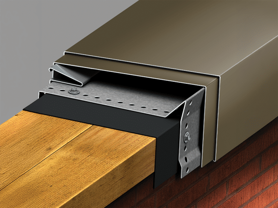
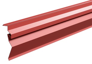
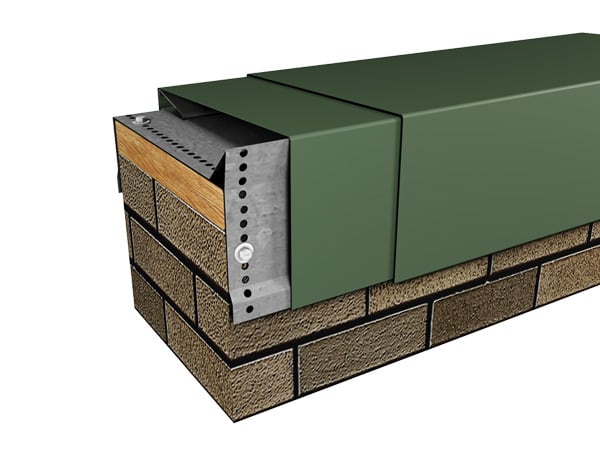
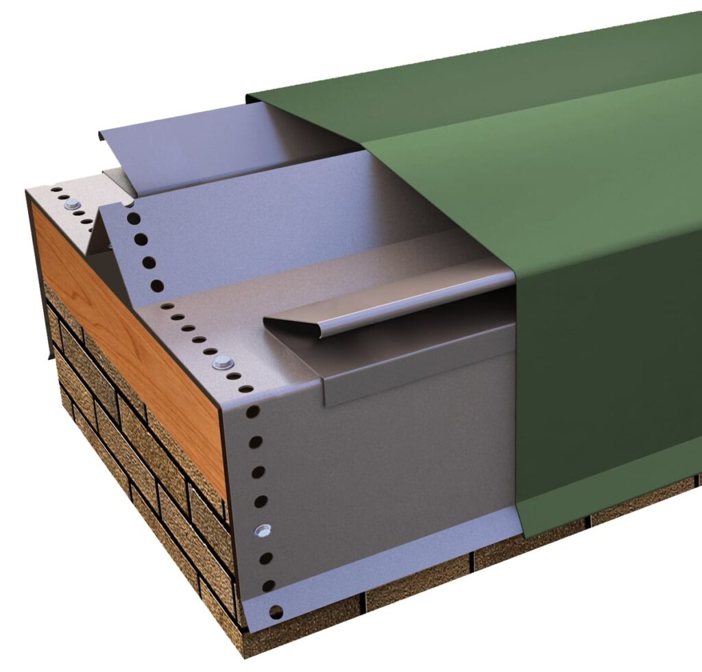
The Anchor-Tite Canted Fascia is a snap-on fascia from Metal-Era's Anchor-Tite family, made for single-ply roof systems. The system pairs the fascia cover with a patented, extruded aluminum anchor bar that terminates the membrane, and installation is non-stripped-in.
Face heights run from 5 1/2 to 13 1/2 in., and a lifetime, 215 mph Anchor-Tite Wind Warranty is available on the system.
Versions
The galvanized waterdam version features a canted waterdam. The existing beveled wood nailer version is made for existing beveled wood nailer edge applications. Both use the anchor bar described below.
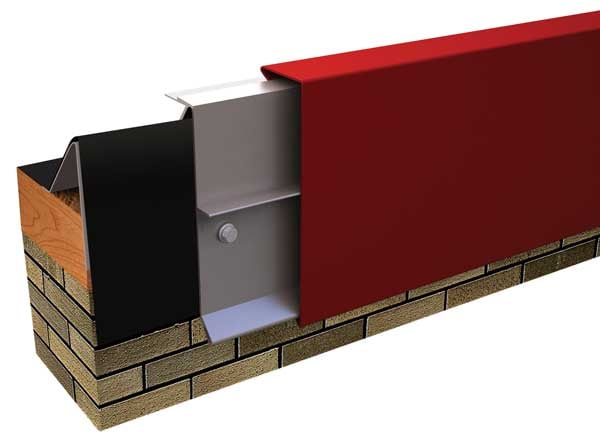
The wood nailer version is drawn over a wood cant block with a 45° profile that is 3 1/2 in. high. The cant block sits on the existing nailer, the roofing membrane runs up the cant, and the extruded anchor bar fastens through the cant block. The drawing is marked ANSI/SPRI ES-1 tested.
Extended versions of both are also made, and radius and custom profiles are available. Fascia extenders are drawn with and without an offset, in lap-joint and splice-plate versions. Miters at angles other than 90° have a separate print approval (No. 11010-1103) and a measurement worksheet. The canted fascia is also drawn for use with a 1.5-in. or 3-in. Eliminailer-T over masonry wall, metal deck or wood nailer.
Data sheets and technical documents
Current files
Archived files
No older reviewed revisions are archived for this product yet.
Sizes and cover materials
Standard face heights are 5 1/2, 7 1/2, 8 1/2 and 10 in., which accommodate multiple nailers and coverage requirements. These four sizes are listed with a one-piece bar. Extended sizes are 9, 10 1/2, 12 and 13 1/2 in.
On the wood nailer version the four standard heights carry the product numbers AEFC-550 (5 1/2 in.), AEFC-750 (7 1/2 in.), AEFC-850 (8 1/2 in.) and AEFC-1000 (10 in.). The extruded bar varies in design at its lower kick on the 5 1/2 in. size, and the 10 in. size is not available in 24-gauge galvanized steel or .040-in. aluminum. Cover coverage should extend a minimum of 1 1/2 in. below the wood blocking where applicable.
Covers are manufactured in 24-gauge galvanized steel, 22-gauge galvanized steel, and .040-in., .050-in. and .063-in. aluminum. The extended sizes are made in 22-gauge steel and in .050-in. and .063-in. aluminum.
Anchor bar, splice plates and fasteners
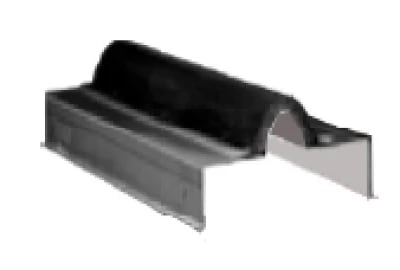
The patented, extruded aluminum anchor bar terminates the membrane, and it can be used to dry in the roof structure. The wood nailer version is covered by U.S. Patent No. 7,451,572. When a roof is replaced, the bar can be removed, cleaned and reinstalled without compromising its strength and appearance.
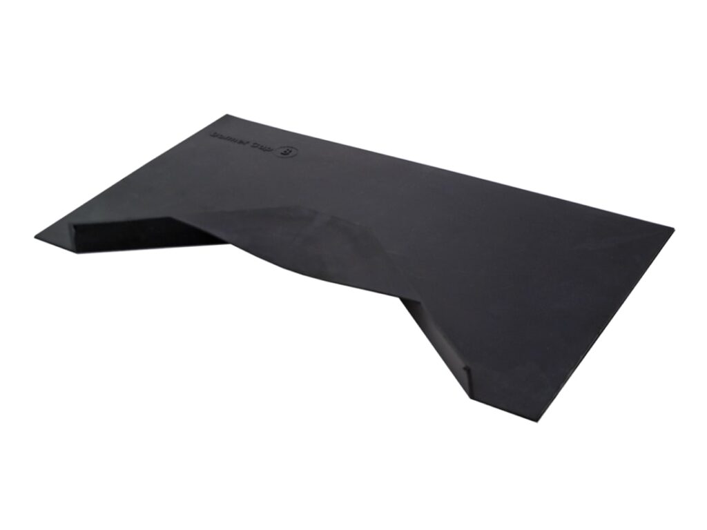
Covers are provided in 12 ft. lengths with pre-punched holes, and the galvanized waterdam cover comes with 3 1/2 in. wide splice plates. The wood nailer version cover is also provided with 3 1/2 in. wide splice plates. The fastening holes are slotted to allow thermal movement of the materials and to place fasteners correctly. Splice plates are interlocking and concealed, which prevents them from migrating under the panels. The EPDM splice plates for the anchor bar and the fasteners are included with the product, and sealant is supplied by others.
On the wood nailer version the anchor bar is fastened with provided #10 x 2 in. stainless steel fasteners at 12 in. on center. The anchor bar slots are 1 1/16 in. long and run diagonally. Fasteners and drive bits are provided.
The design is non-penetrating and needs no stripping-in or heat welding.
Finishes and colors
The color range includes Dark Bronze, Bone White, Cityscape, Almond, Medium Bronze, Sandstone, Sierra Tan, Slate Gray, Stone White and Clear Anodized, and a mill finish is also available.
For Anchor-Tite Canted Fascia, coil-coated standard colors carry a 30-year Kynar 500 finish warranty. Custom post-coated Kynar 500 colors include a 10-year finish warranty, with 20 years available on request. Anodized finishes are covered for 5 years, with no warranty on coil anodizing and a 10-year option for post-coat Class 1 batch anodizing.
Wind testing, approvals and warranty
The galvanized waterdam version is tested per ANSI/SPRI/FM 4435/ES-1 to comply with the International Building Code. It is Factory Mutual approved for wind uplift protection. It is Miami-Dade approved (No. 23-0912.08, 12/11/28) to comply with the High Velocity Hurricane Zone of the Florida Building Code. The print approval for the canted fascia on a 1.5-in. Eliminailer-T over metal deck carries the FM Approved mark, and the wood nailer print approval is marked ANSI/SPRI ES-1 tested.
On Anchor-Tite Canted Fascia, the Lifetime, 215 mph Anchor-Tite Wind Warranty is available on all Metal-Era manufactured Anchor-Tite products. It covers replacement or repair of any portion of the system that has failed because of a defect in Metal-Era supplied materials, and it covers the roof edge for the lifetime of the roof on which the system was first installed.
Miters, scuppers and accessories
Miters are factory fabricated, which removes the need for field fabrication. On the galvanized waterdam version, scuppers and drainage accessories are factory fabricated as well. The order quantities for that version cover outside and inside miters at 90°, overflow scuppers, spillout scuppers and downspout scuppers.
Both the wood nailer and Eliminailer-T versions are available in lineal feet in 12 ft. lengths, outside and inside miters at 90°, and overflow, spillout and downspout scuppers in styles A and B. Downspout style A is a tapered 1 1/2 in. drop and style B is flat. Miters that are not 90° are covered by print approval No. 11010-1103.
Installation of the wood nailer version
The wood nailer installation instructions (drawing 11110-24626) are numbered as follows.
- Step 1, roofing membrane. In a single-ply application a single layer of roofing material is applied over the cant block and extends over the front face of the nailer, making sure the nailer is covered. In built-up or modified applications the first layer of roofing extends over the face of the nailer, and the flashing material extends up the cant block under the extruded anchor bar. The roof membrane manufacturer's general recommendations for applying materials over the roof edge are followed.
- Step 2, scuppers. Spillout or downspout scuppers are installed at predetermined locations where applicable. The roof membrane is installed under the scupper, and the scupper flange is set in a continuous bead of non-curing sealant. The membrane manufacturer's recommendations for stripping in the scupper are followed.
- Fastener position in the slot. With diagonal slots, the fastener goes at the top of the slot for a single nailer installation and at the bottom of the slot when a 1/2 in. cover board is used, when fastening into masonry, or when fastening into Eliminailer-T. If the slots are all horizontal rather than diagonal, the fastener goes in the center of the slot.
- Step 5, miter bar. The miter anchor bar is installed with one anchor bar splice plate under each end of the miter bar and fastened with 2 in. hex head stainless steel fasteners. The spillouts and scuppers are then located and installed with fasteners and splice plates.
- Step 6, anchor bar. The 12 ft. anchor bar sections are positioned overlapping the bar splice plate, with a 3/8 in. space between anchor bars. A bar splice plate is installed at the other end of each bar section. The bar is fastened 12 in. on center through the slotted holes with the provided 2 in. fasteners, and sections are field cut as necessary.
- Step 7, miter covers. Miter covers are installed first, with one splice plate under each end of the two-piece miter cover. The cover with the 90° tab engages onto the bottom of the anchor bar and rotates up and over the anchor bar miter until engaged along its entire length. The steps are repeated for the miter cover without the 90° tab.
- Step 8, fascia covers. The 12 ft. fascia cover sections are installed with a 3/8 in. gap between sections and one splice plate under the far end of each section. Each cover hooks its lower edge onto the anchor bar and rotates up and over the bar until engaged along the entire length of the section. Sections are field cut where necessary with a fine tooth hacksaw. The protective film is removed before each fascia section is installed.
Eliminailer-T and fascia extender configurations
The metal deck print approval (drawing 11010-28233) covers the canted fascia with the 1.5 in. Eliminailer-T version and carries U.S. Patent No. 9,878,023 B1. The cover is 12 ft. long and is provided with 3 1/2 in. wide splice plates. The formed cant is 24-gauge galvanized steel, and a 4 in. wide 24-gauge galvanized retainer clip is set 6 ft. on center. The Eliminailer-T is a .100 in. extruded aluminum part (ELI-T-1555, print approval 11018-27991) that sits under the rigid polyiso roof insulation and is fastened with #12-14 x 1 in. Tek 3 screws at 12 in. on center, provided with the product.
Product numbers for this configuration are T-AEFC-55, T-AEFC-75, T-AEFC-85 and T-AEFC-100, for the 5 1/2, 7 1/2, 8 1/2 and 10 in. heights. The 10 in. size is not available in 24-gauge galvanized steel or .040-in. aluminum. The Eliminailer-T version has slotted holes staggered 6 in. on center, #14 x 1 1/4 in. fasteners provided, and suits metal deck of 22 gauge or 20 gauge only.
The fascia extender with offset has pre-slotted holes at 12 in. on center and includes a continuous 22-gauge galvanized cleat. It is offered in 24-gauge and 22-gauge galvanized steel and .040-in., .050-in. and .063-in. aluminum, and the .050-in. and .063-in. aluminum versions are provided with 3 1/2 in. wide concealed splice plates because of material thickness. Welded miters and accessories are furnished as standard, and lap joint splice plates are an orderable quantity.
The lap joint fascia extender installation instructions (drawing 11114-1547) start with the miters. The continuous cleat is positioned true and level and fastened 12 in. on center. The drip edge of each extender hooks onto the cleat and is fastened 12 in. on center. Panels are installed from right to left as seen from the rooftop, with a 1 in. lap at the notch provided at each joint, and are field cut as necessary. The protective film is removed immediately after installation.