Hi-Perf Ridge Vent
- Manufacturer
- Metal-Era
- Product
- Hi-Perf Ridge Vent
- Status
- Current
- Market
- United States
- Latest revision
- C
- Latest file date
- November 18, 2015
- Last verified
- October 14, 2026
Overview
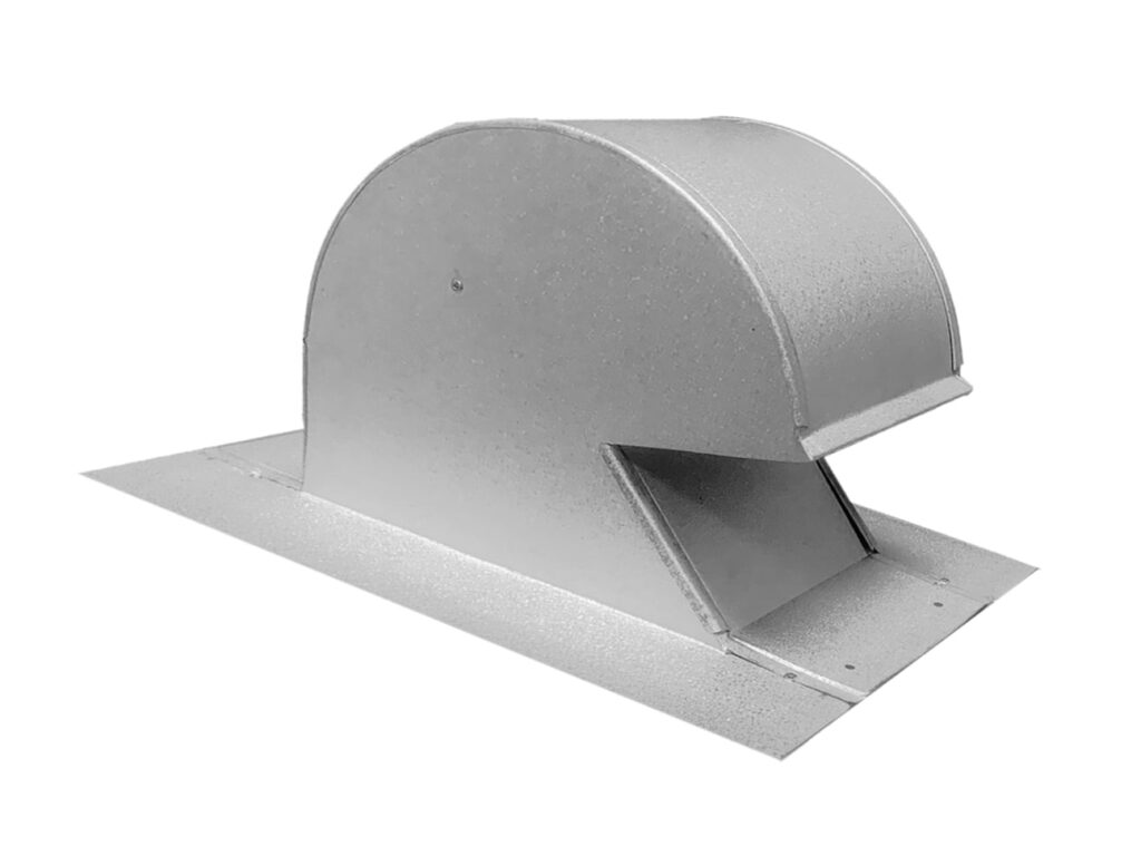
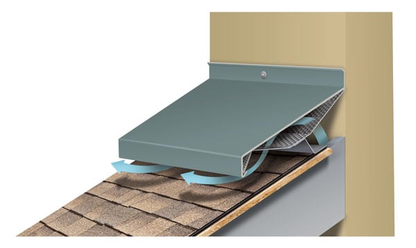
Hi-Perf Ridge Vent is a ridge ventilation product in Metal-Era's Hi-Perf family of sloped roof ventilation systems. It is built entirely of metal: a formed cover sits above an expanded metal support screen, and the assembly is fastened to a continuous 20-gauge galvanized Z bracket. The cover is supplied in 12'-0" lengths with pre-punched holes, and the fastening holes are slotted so the metal can move with temperature changes.
The vent is made to order for each roof. It is engineered to the individual job, and it is manufactured to bend to one specific roof pitch. The all-metal construction does not compress under stress and withstands heavy snow loads. It is weatherproof and bug-proof.
The system is used on existing shingled roofs, where an opening is cut at the ridge and the vent is set over it. This page covers two versions of the same product: Slope to Slope Shingled, for a ridge where two roof slopes meet, and Sloped Roof Meets High Wall, for a roof slope that ends against a higher wall.
Slope to slope and high wall versions
The two versions share the same cover, expanded metal support screen, cover plates, endcaps and Z bracket. They differ in where the vent sits and in what is fastened to what.
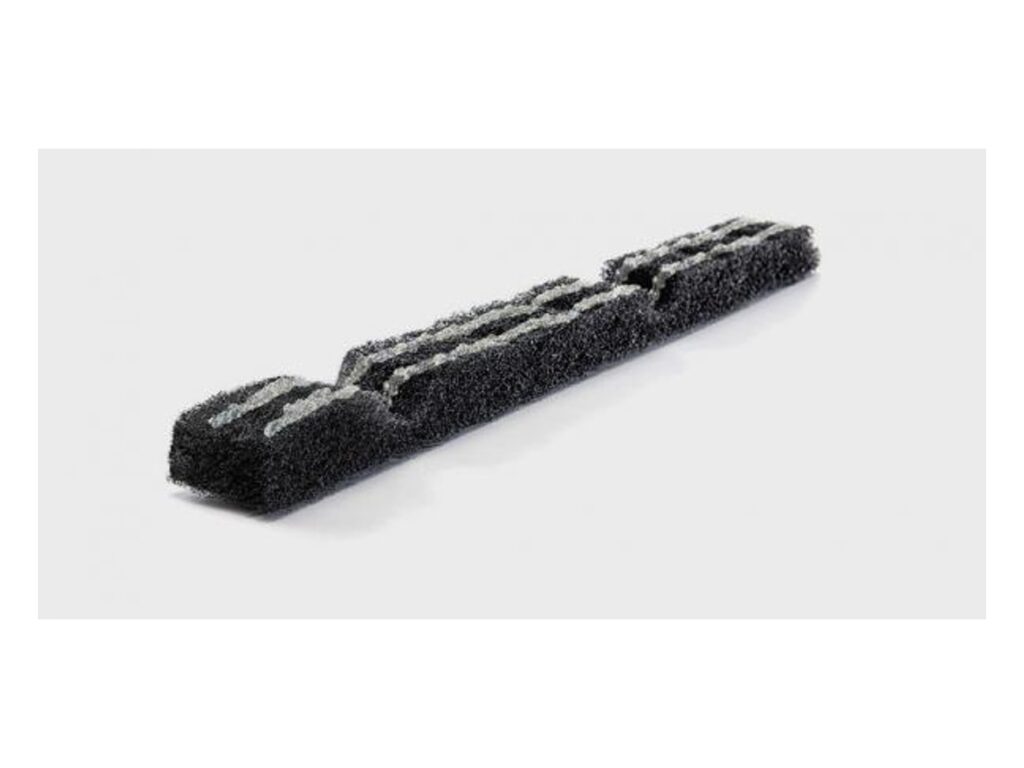
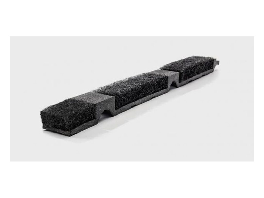
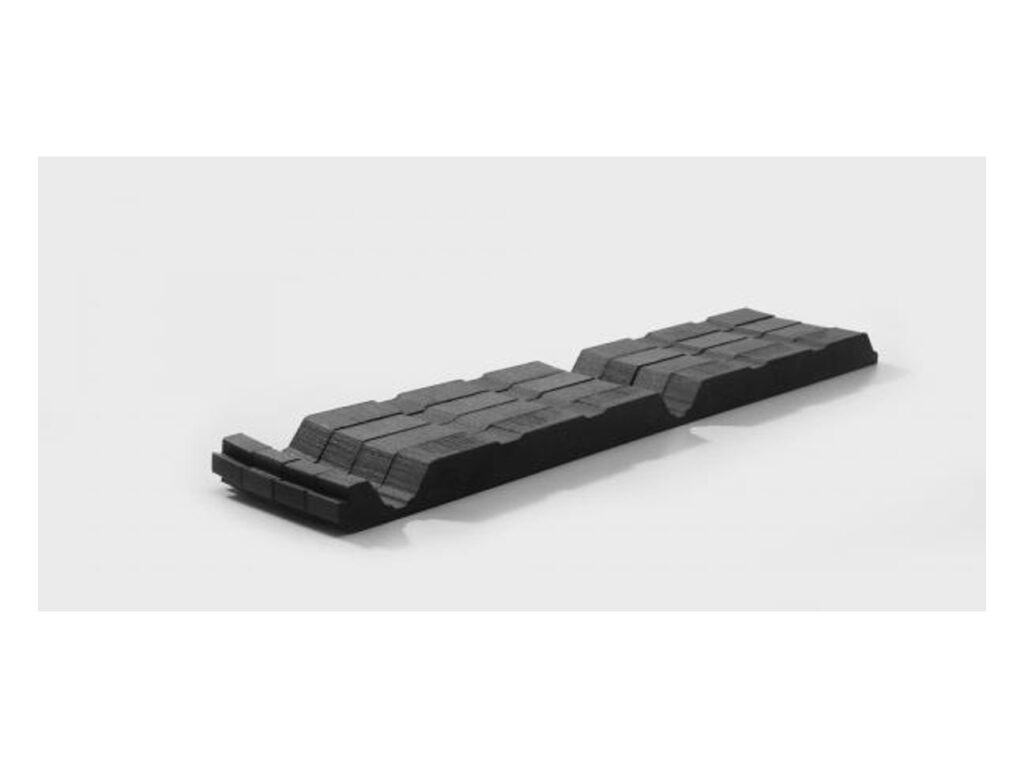
- Slope to Slope Shingled is centered over an opening cut along a ridge. The cover is carried on intermittent spacers set 12 in. on center, which are bent to the roof pitch. Deflectors run along both sides of the vent on the existing shingled roof.
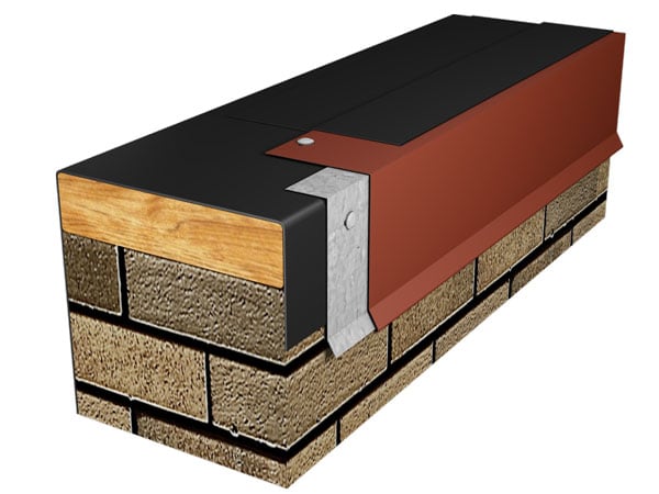
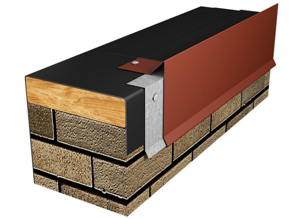
- Sloped Roof Meets High Wall runs along the line where a sloped roof meets a higher wall. The Z bracket is fastened to the roof over OSB or plywood, and the vent is fastened to the wall. The cover has a caulk lip that is sealed against the wall.
Each version has its own product code on the Metal-Era page: HPS for Slope to Slope Shingled and HPSH for Sloped Roof Meets High Wall. Both are ordered by size and cover material.
The Slope to Slope version requires deflectors on any roof pitch less than 4/12. The deflector baffle is required only where the pitch is under 4/12, and a 3 1/2-in. wide deflector baffle is used at deflector joints.
Data sheets and technical documents
Current files
Archived files
No older reviewed revisions are archived for this product yet.
Cover materials and finishes
Covers are made in four materials:
- 24-gauge galvanized steel
- .040-in. aluminum
- .050-in. aluminum
- .063-in. aluminum
All cover plates are included with the product and arrive with it. Sealant is supplied by others.
For Hi-Perf Ridge Vent, standard colors are coil-coated and carry a 30-year Kynar 500 finish warranty. On Hi-Perf Ridge Vent, custom post-coated Kynar 500 colors include a 10-year Kynar 500 finish warranty, and a 20-year warranty is available on request. Anodized finishes carry a 5-year warranty. Coil anodized finishing has no warranty. Post-coat Class 1 batch anodizing is available with a 5-year warranty, with an option to raise it to 10 years for an upcharge.
The cover materials for both versions are 24-gauge galvanized steel and .040-in., .050-in. and .063-in. aluminum, plus an option for other materials.
Ventilation, testing and approvals
Hi-Perf Ridge Vent is intended to exhaust the airflow required at the ridge, which limits heat buildup and moisture accumulation under the roof covering. Metal-Era calculates the net free area (NFA) for the project, and the ventilation guarantee applies when the system is designed to that calculated NFA.
The Slope to Slope Shingled version passed the TAS 100(A) water infiltration test. Miami-Dade County approval 18-0615.06 (7/11/23) covers the Slope to Slope Shingled version in the High Velocity Hurricane Zone of the Florida Building Code. The Miami-Dade version also carries the earlier Notice of Acceptance 12-1218.03 (12/11/18).
The Sloped Roof Meets High Wall version holds Miami-Dade County approval No. 18-1015.05, dated 2/13/24, for the same zone.
Both versions are engineered to withstand winds up to 130 mph.
Components and fastening
A Slope to Slope assembly is made up of these parts:
- a ridge vent cover in 12'-0" lengths;
- a .050 expanded metal support screen, with a 7/16-in. hem shown on the drawing;
- a continuous 20-gauge galvanized Z bracket;
- intermittent spacers at 12 in. on center;
- 8-in.-wide cover plates at each cover joint;
- endcaps;
- deflectors in 12'-0" lengths on both sides of the vent;
- 3 1/2-in.-wide deflector baffles at deflector joints.
The Sloped Roof Meets High Wall assembly uses a cover, a .050-in. expanded metal support screen, a continuous Z bracket, 8-in.-wide cover plates and endcaps.
Fasteners and sealant are supplied by others. Non-curing sealant goes under the Z bracket and at cover joints, and 100% silicone sealant goes on the deflectors. All fasteners must meet a minimum of 240 lb. pull-out for the substrate. Installers wear protective eye wear and do not overdrive fasteners, because stripping can occur at high driver torque. The recommended driving tool is a 600 to 800 rpm electric drill with a depth-sensing nose piece, and an impact-type tool is not used. The protective plastic film comes off each cover section before it is installed.
Slope to slope installation sequence
The Slope to Slope Shingled instructions run in nine numbered steps:
- Prepare the ridge. Cut the opening at the ridge to the X dimension, and end the opening 6 in. before a gable or hipped end.
- Bend the ridge vent until the spaces in the intermittent spacers are closed. It is manufactured to bend for one specific roof pitch, and this can be done on the ground or on the roof.
- Set the Z brackets. Apply a generous bead of non-curing sealant along the entire length of the bottom of the flange, to prevent moisture entry under the Z.
- Set the ridge vent in place, centered over the ridge opening, with the bends on top of every spacer facing away from the end of the roof. Fasten through the pre-punched slotted holes in the spacers at 12 in. on center, and through the slotted holes in the Z brackets at 12 in. on center. The Z brackets lap 1 in., and the expanded metal support screen butts together.
- Fit the endcaps by sliding each onto the expanded metal support screen. Remove the protective film immediately.
- Slide the cover onto the expanded metal support screen. Leave a 3/8-in. space at joints for thermal expansion, and field cut where needed with a fine-tooth hacksaw. Remove the protective film immediately.
- Fit cover plates at joints. Apply a generous bead of non-curing sealant to each side of the joint, hook the cover plate onto the cover and rotate it into place. Pop rivet into the cover plate on one side of the joint, the side with the 90-degree drip angle, to prevent migration.
- Install the deflectors. Apply 100% silicone sealant as shown, start at the endcaps, and fasten 12 in. on center through the pre-slotted holes. Lap pieces 1 in. at joints, which leaves a 1-in. gap between pieces, and place silicone sealant at the slotted fastening holes. Field cut with a fine-tooth hacksaw or snips where necessary.
- Place the 3 1/2-in. deflector baffle at every deflector joint. Fasten one side of the baffle through the deflector into the existing roof.
High wall installation sequence
The Sloped Roof Meets High Wall instructions run in eight numbered steps:
- Prepare the ridge. Cut the opening at the X dimension.
- Mount the Z brackets. Apply a generous bead of non-curing sealant to the bottom of the flange, then fasten the brackets to the roof 6 in. on center through the pre-punched slotted holes. Lap the Z brackets 1 in. Foam or sealant is placed between the Z and the high wall, over the OSB, on the last 6 in. at both ends.
- Place the expanded metal support screen centered over the Z bracket and fasten it to the bracket 12 in. on center. Lap support screens 1 in.
- Snap the endcap into place, starting at the sloped end. Hook the expanded metal support screen into the cover lip and rotate the endcap downward. Remove the protective film immediately.
- Snap the cover into place, starting at the sloped end, by hooking the support screen into the cover lip and rotating the cover downward. Leave a 3/8-in. space at joints for thermal expansion.
- Fasten to the wall 12 in. on center through the pre-punched slotted holes. One fastener is required for each endcap.
- Continue installing the cover with a 3/8-in. space at joints, field cutting where needed with a fine-tooth hacksaw. Apply non-curing sealant to each side of the joint, hook the cover plate onto the cover and rotate it into place, then fasten one screw centered in the cover plate to prevent migration.
- Apply a generous bead of non-curing sealant between the caulk lip and the high wall, to prevent moisture entry behind the caulk lip.
Wind and ventilation warranty
The Hi-Perf 20-Year, 130 mph Wind and Ventilation Warranty is available on all Metal-Era manufactured Hi-Perf ventilation systems. It guarantees that the system will provide proper ventilation for the project when designed to the Metal-Era calculated NFA, will withstand winds of up to 130 mph, and will be free of defects in Metal-Era supplied materials.
The warranty covers repair or replacement of the system for 20 years or the lifetime of the roof on which it was originally installed, whichever comes first. The finish warranties described above are separate.