Perma-Tite Expansion Joint
- Manufacturer
- Metal-Era
- Product
- Perma-Tite Expansion Joint
- Status
- Current
- Market
- United States
- Latest revision
- J
- Latest file date
- October 4, 2021
- Last verified
- October 14, 2026
Overview
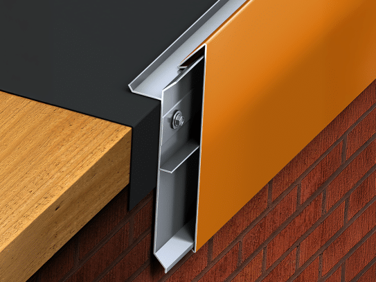
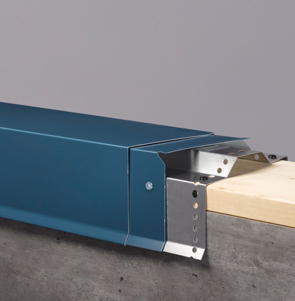
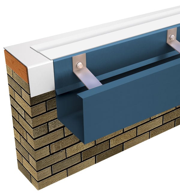
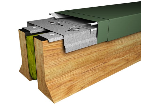
Perma-Tite Expansion Joint is a covered expansion joint from Metal-Era's Perma-Tite family. It allows thermal movement at two kinds of locations: between two roof systems, and between a roof system and a terminating wall. A formed metal cover snaps onto a continuous cleat that is screwed to wood curbs, and a condensation seal with insulation sits in the gap below the cover. No fasteners are exposed and no cover plates or lap joints show at the seams.
This page covers the two standard versions, Roof to Roof and Roof to Wall. Metal-Era also makes 3-axis versions of both, which allow vertical motion for live loads without losing thermal or seismic motion; those are separate products.
The cover is supplied in 12'-0" lengths with pre-punched fastening holes. The holes are slotted so the metal can move with temperature changes and the fasteners land in the right place and spacing. The product attaches to wood framing on new or existing roofs, and the continuous cleat protects the joint from wind-driven rain. The insulated condensation pocket guards against condensation caused by internal building temperatures.
Expansion joints like this one are part of the perimeter and transition metalwork used to finish low-slope roof assemblies, where a roof meets another roof or a rising wall.
Roof to Roof and Roof to Wall versions
The two versions use the same cover, cleat and splice-plate system and differ in what sits on each side of the gap.
- Roof to Roof: the joint closes the gap between two wood curbs, one fixed and one free. A 24-gauge galvanized continuous rail is nailed to the top of each curb, and the continuous cleat spans both curbs and extends beyond the free side.
- Roof to Wall: the joint closes the gap between a wood curb and the wall. A 24-gauge galvanized continuous curb rail goes on the curb, and a 20-gauge galvanized surface mount continuous rail is fastened to the wall with its center 1/2" above the top of the curb. The cover is fastened to the wall at 12" on center through pre-slotted holes.
Curbs are typical wood curbs with a cant, supplied by others, with a minimum curb width of 1 1/2". The face size is 2 1/2" minimum and 6" maximum on both versions.
On the Roof to Roof version the splice plate is 12" wide and carried on 8"-wide, 20-gauge galvanized anchor cleats placed at 3'-0" on center. The cleat is a 20-gauge galvanized continuous cleat fastened through slots into the curbs.
Data sheets and technical documents
Current files
Archived files
No older reviewed revisions are archived for this product yet.
Cover materials and finishes
Covers are manufactured in these materials:
- 24-gauge galvanized steel
- 22-gauge galvanized steel
- .040" aluminum
- .050" aluminum
- .063" aluminum
For Perma-Tite Expansion Joint, coil-coated standard colors carry a 30-year Kynar 500 finish warranty. Custom post-coated Kynar 500 colors carry an included 10-year finish warranty, and a 20-year warranty is available on request. Anodized finishes carry a 5-year warranty. No warranty is available for coil anodized finishing, and Post-coat/Class 1 Batch Anodized can be raised from 5 to 10 years for an upcharge.
For Perma-Tite Expansion Joint, ten express colors are offered: Dark Bronze, Bone White, Cityscape, Almond, Medium Bronze, Sandstone, Sierra Tan, Slate Gray, Stone White and Clear Anodized. Express colors apply to 24-gauge, .040" and .050" covers only. All colors are also available in mill finish.
Cleat, splice plates and fasteners
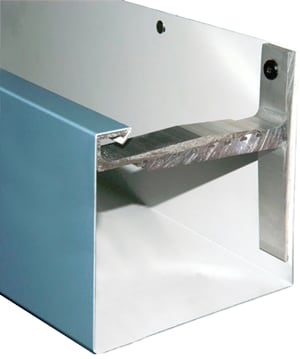
The system includes a special articulating cleat that allows four-way movement for the expansion and contraction of the roof. Shouldered washers, Tapcon screws, galvanized ring shank roofing nails and stainless steel screws are provided with it.
- The continuous cleat is secured with #10 x 1 1/2" stainless steel screws with shouldered washers at 18" on center, through the cleat into the curbs.
- The continuous rails on the curbs are nailed down at 24" on center with 1 1/4" galvanized ring shank roofing nails.
- On the Roof to Wall version, 1/4" x 1 3/4" Tapcon fasteners with shouldered washers go through the cleat into the wall at 18" on center, and the slots in the surface mount rail are 9/32" x 3/8" at 12" on center.
- Fasteners for masonry on the wall rail are supplied by others.
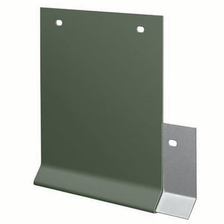
Each joint between cover lengths uses a concealed splice plate. A raised stop on the plate prevents it from migrating under the cover panels, and each plate comes with factory-applied dual non-curing sealant strips. Covers are installed with a 3/8" space at each splice joint to allow for thermal expansion.
Miters and accessories are fabricated with a non-penetrating quicklock joint and factory sealed watertight. Welded miters and accessories are available for a surcharge.
Miters, endcaps and endwall flashings
Factory-fabricated accessories remove the need for field fabrication of corners and ends. Both versions are ordered with outside miters, inside miters and endcap inserts, with the lineal feet counted in 12'-0" lengths.
- Roof to Roof: endcap inserts and endwall flashings are ordered without a left or right hand.
- Roof to Wall: right-hand and left-hand endcap inserts and right and left endwall flashings are ordered separately, as seen from the roof.
- Endwall flashings are made in .040" mill finish, painted or welded only.
For corners, the curbs are field cut at a 90° angle and the condensation seal, batt insulation and continuous rails are installed along each leg. A Non 90° Angle for Coping measurement worksheet, for use without a protractor, is published for the Roof to Wall version.
Installation sequence, Roof to Roof
Roof to Roof installation runs through eleven numbered steps in this order:
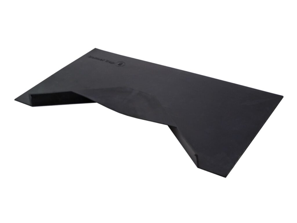
- Condensation Seal: the seal is inserted into the gap between the curbs with a pocket at least as deep as the width of the joint, lapped 6" and sealed at every membrane joint, folded over and held to the wood curb with contact adhesive, then trimmed even with the outside edges of the curbs. Fiberglass insulation goes into the pocket.
- Continuous Rails: the galvanized steel rails go on top of the curbs and are nailed at 24" on center.
- Miters: curbs are cut at 90°, and steps 1 and 2 are repeated at the corner.
- Miters: the miter cleat is laid over the curbs with its slots centered on the curbs, overhanging the free side, which is the same side as the vertical slots. It is fastened with the stainless screws and shouldered washers, washers extruded side down. The release paper comes off the VHB tape on the anchor clips and miter corner clips, and the anchor clips and the splice plate are set.
- Miters: the miter cover is pressed straight down until it snap locks on both legs.
- Endcaps: the continuous cleat is placed over the curbs, with its slots facing the same way as the miter cleat if a miter came first.
- Endcap Inserts: anchor clips go between the first and second sets of slots, then every 3'-0". The endcap insert is placed into a 12'-0" cover section, pop riveted and sealed with non-curing sealant inside along the seams. The endcap section hooks on the free side of the cleat and rotates into place, and the rear leg snaps on.
- Continuous Cleat: the cleat is fastened along the run in the same way.
- Anchor Clips: the 8"-wide clips are centered between slots at 3'-0" on center.
- Splice Plates: plates are centered on the anchor clips at joints, 12'-0" on center, after the release paper is taken off the sealant strips.
- Expansion Joint Cover: each section hooks onto the free side of the cleat, rotates into place and snaps on. Field cuts are made with a fine-tooth hacksaw or snips, and the protective film comes off immediately.
The screws are not overdriven into the cleat, so that they do not restrict movement.
Installation sequence, Roof to Wall
The Roof to Wall instructions open with the same condensation seal, continuous rail and miter steps. The seal is secured to the wood curb and runs up the wall to a height of 1" above the curb. The curb rail is nailed to the curb at 24" on center, and the surface mount rail is fastened to the wall with one fastener in the middle and one at each end.
Outside miters and inside miters are separate steps. The miter cleat is laid with its vertical flange against the wall and extends beyond the curb. Cleats finish flush with the outside of the continuous curb rail on an outside miter and flush with the inside of the curb rail on an inside miter. One cleat overlaps the other at the corner. Each is fastened with #10 x 1 1/2" stainless steel screws into the curb and 1/4" x 1 3/4" Tapcons into the wall, and non-curing sealant is applied to the top lip of the surface mount rail. The next step, Miter Cover, places splice plates into each end of the miter cover and installs the assembly straight onto the miter cleat.
Wind warranty
For Perma-Tite Expansion Joint, a 20-year, 120 MPH Perma-Tite Wind Warranty is available on orders that call for it. It gives a maximum of 20 years and 120 MPH of coverage for repair or replacement of any portion of the roof edge system that has failed because of a defect in Metal-Era supplied materials. The finish warranties above are separate.