Creative Design Reveal Coping
- Manufacturer
- Metal-Era
- Product
- Creative Design Reveal Coping
- Status
- Current
- Market
- United States
- Latest revision
- K
- Latest file date
- June 20, 2023
- Last verified
- October 14, 2026
Overview
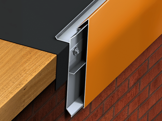
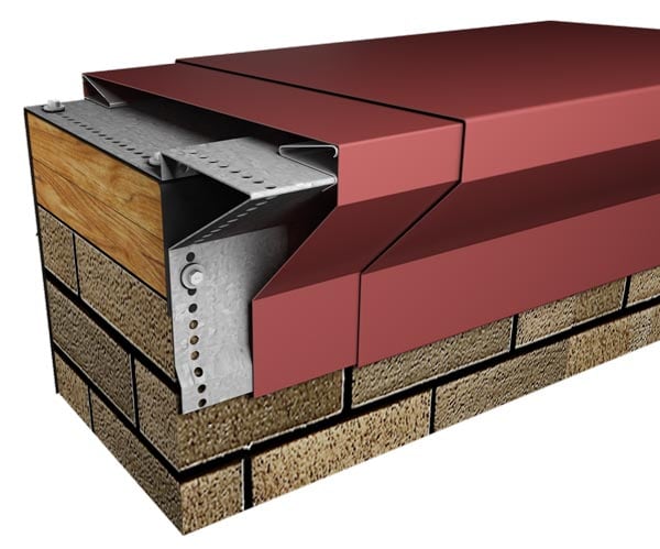
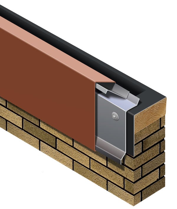
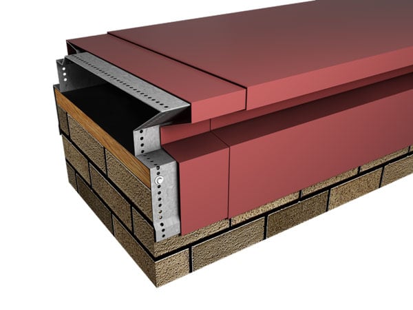
Creative Design Reveal Coping is a metal parapet coping from Metal-Era's Creative Design Series. It is made for parapet conditions where the slope has to be created: the cover steps down from the inside face to the outside face in a reveal profile. The cover snaps onto galvanized steel anchor clips that carry factory-applied stainless-steel springs, so the system is attached without adhesives and without crimping. Covers are supplied in 12-ft. lengths and are custom fabricated to the sizes an order calls for.
Reveal is one of six versions in the series. The others are Bold Face, Bullnose, Cornice, Leak-Tite and Stone-Look, each with its own size range and materials. Reveal wall sizes start at 7 1/4 in.
On a parapet, the roof membrane is positioned on top of the wall and covers the treated wood nailers or substrate completely, with a 1/2-in. minimum of excess membrane beyond the nailer where a nailer is used. The coping then caps that termination. Metal-Era's Creative Design coping is one of the perimeter metal components used to finish low-slope roof assemblies at the roof edge.
Sizes and face dimensions
Reveal covers are sized by the wall they cap and by the heights of the two faces:
- Outside face: 7 3/4 in. minimum and 12 in. maximum on the print approval and 7.75 in. to 12 in. on the sell sheet
- Inside face: 6 1/2 in. minimum and 10 in. maximum.
- Wall size: 7 1/4 in. minimum. The maximum is 16 in. on the sell sheet and 24 in. on the print approval, which together span 7 1/4 in. to 24 in.
The outside face and the inside face cannot be greater than the wall size plus 1 in. A 3/8-in. space is provided in the cover for variations in the wall.
For Creative Design Reveal Coping, covers are ordered by stretch-out, the flat width of metal needed to form the profile. Category I covers a stretch-out of 0 to 9.375 in., Category II over 9.4375 to 17.375 in., Category III over 17.4375 to 25.375 in., Category IV over 25.4375 to 41.375 in. and Category V over 41.4375 to 65.375 in.
Data sheets and technical documents
Current files
Archived files
No older reviewed revisions are archived for this product yet.
Cover materials and finishes
The Reveal cover is formed from one of three materials:
- 22-gauge galvanized steel
- .050-in. aluminum
- .063-in. aluminum
The thinner 24-gauge steel and .040-in. aluminum covers listed for Bold Face are not listed for this version.
On Creative Design Reveal Coping, standard colors are coil-coated with Kynar 500 and carry a 30-year finish warranty. For Creative Design Reveal Coping, custom post-coated Kynar 500 colors include a 10-year finish warranty, and a 20-year Kynar 500 finish warranty is available on request. Anodized finishes carry a 5-year warranty. Coil-anodized material has no finish warranty, and post-coat Class 1 batch anodizing can be raised from 5 to 10 years at extra cost.
On Creative Design Reveal Coping, ten express colors are offered: Dark Bronze, Bone White, Cityscape, Almond, Medium Bronze, Sandstone, Sierra Tan, Slate Gray, Stone White and Clear Anodized. All colors are also available in a mill finish.
Anchor clips, splice plates and fasteners
Each anchor clip is 12 in. wide and formed from 20-gauge galvanized steel. Stainless-steel springs are attached to the clips at the factory and hold the cover under positive spring loading once it is snapped into place. The installation drawing sets the clips at 3 ft. on center along the run. Clip spacing on the print approval is determined by the manufacturer.
Every joint between 12-ft. cover lengths is backed by an 8-in.-wide concealed splice plate. Each plate carries dual strips of non-curing isocryl butyl sealant, applied at the factory. The plates seal the joint and allow for thermal movement of the materials. Fastening holes in the clips are pre-punched.
Fasteners ship with the coping. The substrate is named on the order as wood, masonry or metal, and wood-substrate fasteners are provided where no substrate is given. For Creative Design Reveal Coping, fasteners must be corrosion resistant and rated for a minimum 250-lb. pullout force in the substrate being used. An extra outside-face fastener is needed only on faces of 9 in. and above.
Testing and warranty
The Reveal version is tested to ANSI/SPRI/FM 4435/ES-1, the roof-edge standard referenced by the International Building Code. Within the Creative Design Series, FM Approved and Miami-Dade County Approved are listed for the Leak-Tite version only. Bold Face, Bullnose, Cornice and Stone-Look carry no testing listing.
A 20-year, 120 mph Creative Design Series wind warranty is available on orders that call for it. It provides a maximum of 20 years and 120 mph coverage for repair or replacement of any portion of the roof edge system that has failed because of a defect in Metal-Era supplied materials. The finish warranties described above are separate.
Miters, endcaps and accessories
Corners, ends and transitions are factory fabricated, which removes the need for field fabrication. On the Reveal coping all miters and accessories are welded; quicklock joints are not available. On Creative Design Reveal Coping, welded accessories require a minimum material thickness of .050 in.
Reveal accessories include 90-degree outside miters, 90-degree inside miters, right endcaps and left endcaps. Further accessories published for the product are:
- non-90-degree miters, with a separate measurement worksheet for use without a protractor;
- step-up coping miters, left and right hand;
- peak and valley miters;
- Space Maker outside coping miters;
- straight coping transitions, with or without capped ends, and transition coping miters;
- inside and outside coping miters with endcaps, left and right hand;
- inside T and outside T miters;
- Z coping miters, left and right hand;
- pilaster caps.
Z coping miters and step-up miters can be ordered with custom leg lengths by modifying the drawing dimensions.
Installation sequence
Miters are installed first. The numbered steps run as follows:
- Corner support clips: locate and fasten one 5 1/2-in.-wide galvanized corner support clip to the wall.
- Miter splice plates and anchor clips: position the splice plate in the center of the anchor clip, and install the assembly into each end of the corner.
- Miter: hook the miter onto the corner clip and rotate it into place, then secure it at the exposed edge of the anchor clips with the provided fasteners for the substrate.
- Endcap anchor clips: locate and fasten the galvanized anchor clips to the wall with the provided fasteners for the substrate.
- Endcap splice plates: remove the release paper from the top of the factory-applied sealant strips and place the splice plate onto the second anchor clip.
- Endcap: hook the outside face of the endcap over the anchor clips and rotate it into place, then engage the rear leg onto the anchor clips by pressing downward until the snap lock occurs.
- Anchor clips: locate and fasten galvanized anchor clips to the wall at 3-ft. centers with the provided fasteners for the substrate.
- Splice plates: place the splice plate onto the anchor clips after removing the release paper from the sealant strips.
- Coping: hook the outside face of the coping over the anchor clips, rotate it into place and press downward on the rear leg until the snap lock occurs. A 3/8-in. space is left at splice joints to allow for thermal expansion.
- Completion: continue installing coping in the same way. Where cutting is needed, a fine-tooth hacksaw or snips are used in the field, and the protective film is removed immediately.
For outside face heights under 9 in., the fastener goes in the first full hole from the bend and the third full hole from the drip. Where an EIFS system is used, the cover is fastened through the face with a fastener long enough to penetrate the nailer.