Whirlwind Steel Super Span X roof profile
- Manufacturer
- Whirlwind Steel Buildings
- Product
- Super Span X 24-gauge roof panel, drawing 14-117_R revision 2 (2021)
- Status
- Current
- Market
- United States
- Latest file date
- September 24, 2026
- Last verified
- September 24, 2026
- Archived files
- 1
Overview
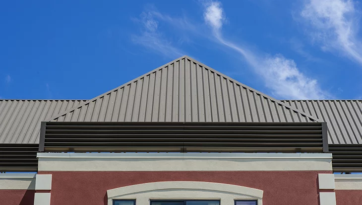
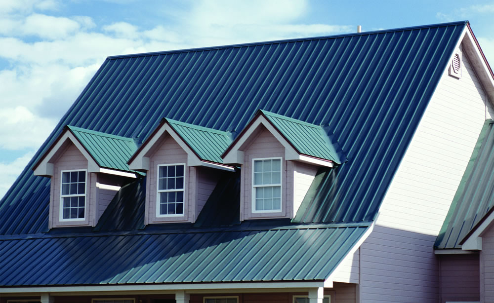
Super Span X is Whirlwind Steel Buildings' exposed-fastener roof and wall panel. It belongs to the Super Span family of screw-down panels and is classed here as a commercial metal roof profile. Whirlwind also calls the panel a PBR panel. The panel has its own measured section, so the PBR name does not describe every panel sold under that label.
The product is an exposed-fastener metal panel of the kind used on commercial and agricultural buildings, the type covered by exposed-fastener metal roof panels. The Super Span family is available in 26, 24 and 22 gauge, and the family is used for both wall and roof applications.
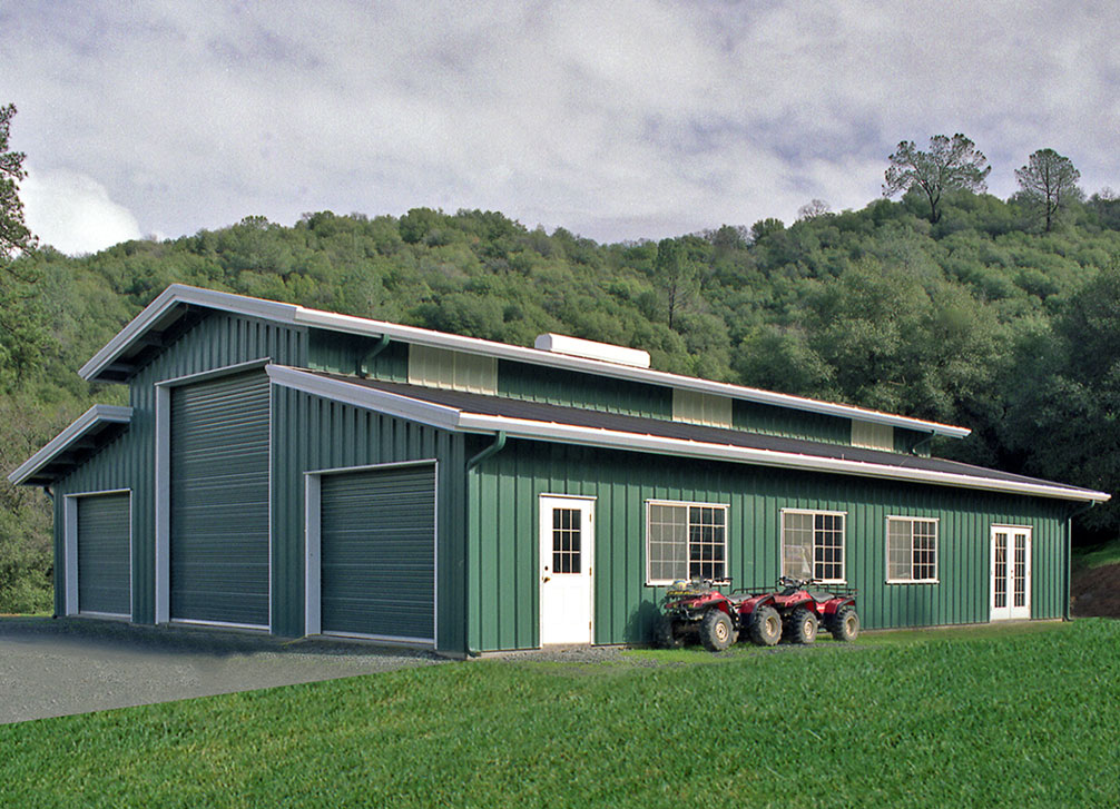
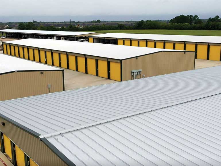
The roof drawing that carries the product is Whirlwind drawing 14-117_R, sheet 1 of 3. It was first dated April 15, 2014 and revised for the second time on March 25, 2021. The dimensions and angles on this page come from revision 2. A Whirlwind photograph shows the panel on the Pineywoods Storage project, installed in 26-gauge Super Span X.
Profile and dimensions
The installed coverage is 36 inches. Tall major ribs repeat on 12-inch centers, which gives three major modules across the cover. Low minor beads repeat at 4-inch intervals between the tall ribs. The drawing also labels an 18-inch rollspace callout.
- Major rib rise: 1.25 inches (1 1/4 inches).
- Major rib crown: 1.00 inch, shown as one-half inch on each side of the centerline.
- Major rib base: 3.3125 inches (3 5/16 inches), with 1.656 inches from the centerline to each base end.
- Major web angle: 47.2312 degrees.
- Minor bead rise: 0.188 inch.
- Minor bead crown: 0.75 inch, made of two 0.375-inch halves.
- Minor bead base: 1.4375 inches, made of two halves of about 0.719 inch.
- Typical bend radius: 0.0938 inch.
The enlarged cross-section on the drawing shows a straight section, an enlarged major rib, a shallow intermediate bead and a separate side-lap view.
Data sheets and technical documents
Current files
Archived files
Side lap and bearing leg
Super Span X carries a bearing leg at the side lap. The Super Span family flyer labels this feature as the bearing leg for Super Span X, and the family side-lap detail shows a 3 5/16-inch base dimension at the major rib. The approved roof drawing shows one outer rib joining the next panel. It marks where side-lap stitching and a continuous tape line sit in the assembly. The roof layout stays at 36 inches of installed coverage once the joint is made.
The drawing does not print a numeric schedule for both free-edge tails, the finished overall panel width or the nesting clearance at the joint.
Materials and coating
The current Miami-Dade notice 25-0701.01 covers a 24-gauge Super Span X steel roof-panel system. The panel-properties block of that notice records the following for the described construction.
- Minimum painted-panel thickness: 0.024 inch.
- Yield strength: 50 ksi.
- Steel coating: AZ55.
- Paint coating: Kynar 500.
The notice was approved August 7, 2025 and runs to July 17, 2030.
Gauges and design properties
The technical erection manual, effective January 1, 2018, lists three gauges for Super Span X. Section properties are calculated under the 2001 edition of the North American Specification for Design of Cold-Formed Steel Structural Members. Ix is used for deflection and Ma is the allowable bending moment.
- 26 gauge, design thickness 0.0170 inch: Fy 80 ksi reduced to 60 ksi, 0.83 psf. Top in compression, Ix 0.0370 in^4/ft and Ma 1.2697 kip-in/ft. Bottom in compression, Ix 0.0323 in^4/ft and Ma 1.6610 kip-in/ft.
- 26 gauge, design thickness 0.0176 inch: Fy 80 ksi reduced to 60 ksi, 0.86 psf. Top in compression, Ix 0.0380 in^4/ft and Ma 1.4057 kip-in/ft. Bottom in compression, Ix 0.0337 in^4/ft and Ma 1.7230 kip-in/ft.
- 24 gauge: Fy 50 ksi, 1.09 psf. Top in compression, Ix 0.0570 in^4/ft and Ma 1.7500 kip-in/ft. Bottom in compression, Ix 0.0467 in^4/ft and Ma 1.8633 kip-in/ft.
For comparison, the Super Span family flyer of January 2025 lists 26, 24 and 22 gauge Super Span with weights of 0.86, 1.09 and 1.35 psf.
Allowable uniform loads
The manual publishes allowable uniform loads in pounds per square foot for spans of 3.0 to 7.0 feet. Live load is limited by bending, shear, combined shear and bending, web crippling and deflection of L/180. Negative wind load is limited by bending, shear, combined shear and bending and deflection of L/180, with the deflection increased by 30 percent per IBC 2003 Table 1604.3. Negative wind load does not consider fastener pullout or pullover, and the weight of the panel is not deducted.
Selected 24-gauge values (Fy 50 ksi) follow.
- Single span at 3.0 feet: negative wind 138.0 psf and positive wind or live load 129.6 psf. At 5.0 feet: 42.5 psf and 39.9 psf. At 7.0 feet: 15.5 psf and 14.5 psf.
- Two-span at 3.0 feet: negative wind 129.6 psf and positive wind or live load 114.8 psf. At 5.0 feet: 46.7 psf and 46.2 psf. At 7.0 feet: 23.8 psf and 23.7 psf.
- Three-span at 3.0 feet: negative wind 162.0 psf and positive wind or live load 130.5 psf. At 5.0 feet: 58.3 psf and 57.2 psf. At 7.0 feet: 29.2 psf and 27.4 psf.
- Four-span at 3.0 feet: negative wind 151.3 psf and positive wind or live load 125.6 psf. At 5.0 feet: 54.5 psf and 53.8 psf. At 7.0 feet: 27.8 psf and 27.6 psf.
Selected 26-gauge values (design thickness 0.0170 inch, Fy 80 ksi) follow.
- Single span at 3.0 feet: negative wind 123.0 psf and positive wind or live load 94.1 psf. At 5.0 feet: 29.4 psf and 25.9 psf. At 7.0 feet: 10.7 psf and 9.4 psf.
- Two-span at 3.0 feet: negative wind 94.1 psf and positive wind or live load 81.8 psf. At 5.0 feet: 33.9 psf and 33.3 psf. At 7.0 feet: 17.3 psf and 17.1 psf.
- Three-span at 3.0 feet: negative wind 117.6 psf and positive wind or live load 92.9 psf. At 5.0 feet: 42.3 psf and 41.4 psf. At 7.0 feet: 20.2 psf and 17.8 psf.
- Four-span at 3.0 feet: negative wind 109.8 psf and positive wind or live load 89.4 psf. At 5.0 feet: 39.5 psf and 38.7 psf. At 7.0 feet: 20.2 psf and 18.9 psf.
Fastening, laps and approvals
The 24-gauge roof drawing calls for panel fastening to the roof supports, stitching at the side laps and continuous sealant along the relevant joint. The end-lap detail requires at least 6 inches of overlap. The approval sets a maximum allowable panel span of 5 feet.
The erection manual includes a Super Span X roof layout and a separately titled light-transmitting-panel installation. The light-transmitting detail has a 4-inch minimum end-lap note and a minimum three-member support condition. It does not name the light-transmitting material.
The Super Span family flyer lists these approvals and tests for Super Span: UL Construction No. 30, 79, 161 and 167; UL 580 Up-Lift tested, Class 90 rated; and UL 2218 hail impact resistant tested, inclined, unlimited, Impact Class 4. It also lists Texas Department of Insurance, Florida Product Approval and Dade County NOA. Super Span X has two Miami-Dade notices: 25-0701.01, with drawing 14-117_R revision 2, and the earlier 16-0211.04.
Earlier revision
Miami-Dade notice 16-0211.04 holds drawing 14-117_R revision 1, dated January 21, 2016. That section prints the same 36-inch cover, 12-inch tall-rib pitch and 1.25-inch rise as revision 2. The notice expired July 17, 2019.